Inst ToolsInst ToolsInst Tools
  • Courses
  • Automation
    • PLC
    • Control System
    • Safety System
    • Communication
    • Fire & Gas System
  • Instrumentation
    • Design
    • Pressure
    • Temperature
    • Flow
    • Level
    • Vibration
    • Analyzer
    • Control Valve
    • Switch
    • Calibration
    • Erection & Commissioning
  • Interview
    • Instrumentation
    • Electrical
    • Electronics
    • Practical
  • Q&A
    • Instrumentation
    • Control System
    • Electrical
    • Electronics
    • Analog Electronics
    • Digital Electronics
    • Power Electronics
    • Microprocessor
  • Request
Search
  • Books
  • Software
  • Projects
  • Process
  • Tools
  • Basics
  • Formula
  • Power Plant
  • Root Cause Analysis
  • Electrical Basics
  • Animation
  • Standards
  • 4-20 mA Course
  • Siemens PLC Course
Reading: Draw the appropriate Pressure Switch Symbol ?
Share
Font ResizerAa
Inst ToolsInst Tools
Font ResizerAa
  • Courses
  • Design
  • PLC
  • Interview
  • Control System
Search
  • Courses
  • Automation
    • PLC
    • Control System
    • Safety System
    • Communication
    • Fire & Gas System
  • Instrumentation
    • Design
    • Pressure
    • Temperature
    • Flow
    • Level
    • Vibration
    • Analyzer
    • Control Valve
    • Switch
    • Calibration
    • Erection & Commissioning
  • Interview
    • Instrumentation
    • Electrical
    • Electronics
    • Practical
  • Q&A
    • Instrumentation
    • Control System
    • Electrical
    • Electronics
    • Analog Electronics
    • Digital Electronics
    • Power Electronics
    • Microprocessor
  • Request
Follow US
All rights reserved. Reproduction in whole or in part without written permission is prohibited.
Inst Tools > Blog > Practical Questions > Draw the appropriate Pressure Switch Symbol ?

Draw the appropriate Pressure Switch Symbol ?

Last updated: June 6, 2018 9:56 am
Editorial Staff
Practical Questions
No Comments
Share
1 Min Read
SHARE

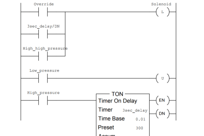
Draw the appropriate pressure switch symbol in this ladder-logic diagram for a low-pressure alarm which turns on a lamp if the oil pressure of an industrial machine ever drops below 10 PSI:

a low-pressure alarm

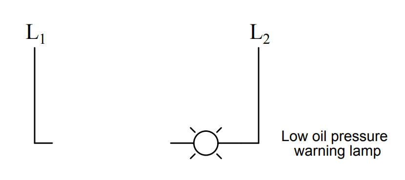
Be sure to specify whether the pressure switch needs to be normally-open (NC) or normally-closed (NC).
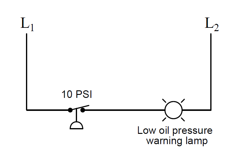
Answer :

As the diagram shows, this needs to be a normally-closed switch.

pressure switch ladder-logic diagram

Share Your Answer / Comments

Credits : by Tony R. Kuphaldt – under CC BY 1.0

Don't Miss Our Updates
Be the first to get exclusive content straight to your email.
We promise not to spam you. You can unsubscribe at any time.
Invalid email address
You've successfully subscribed !

Continue Reading

Questions on Pneumatic Transmitter and Repeater
PT Loop Diagram Faults
Inspecting the Trends of PV and SP on a Process Chart Recorder
Pneumatic Relay Questions
Calculate Hydraulic System Fluid Pressure
Identify the Problem in the PLC Program
Share This Article
Facebook Whatsapp Whatsapp LinkedIn Copy Link
Share
Leave a Comment

Leave a Reply Cancel reply

Your email address will not be published. Required fields are marked *

Stay Connected

128.3kFollowersLike
69.1kFollowersFollow
210kSubscribersSubscribe
38kFollowersFollow

Categories

Explore More

Define Normal Status of a Process Switch ?
Programmable Logic Controller (PLC) Questions and Answers – 17
Calculate Incident Power in Radar Level Measurement
Differential Pressure Measurement across Baghouse
Pneumatic Moment-balance Differential Pressure Transmitter
Surface-mounted Water Pump
Current-to-Pressure Transducer Calibration Table
Programmable Logic Controller (PLC) Questions and Answers – 1

Keep Learning

level control system

Practical Process Control System Questions & Answers – 11

Explain What these Spool Valve Represent

Explain What these Spool Valve Symbols Represent?

Programmable Logic Controller (PLC) Questions and Answers

Programmable Logic Controller (PLC) Questions and Answers – 7

Determine the statuses of all lamps and relay coils in the circuit

Determine the Status of Lamps and Relays in the Circuit ?

Pneumatic Amplifying Relay

Determine Effect of Each Fault for Pneumatic Force-balance System

Identify Instrumentation Terms in Water Supply System

Identify Instrumentation Terms in Water Supply System

How Much Pressure indicated by Micromanometer

How Much Pressure Indicated by Micromanometer?

hydrostatic interface measurement calculation

Hydrostatic Pressure Measurement Questions

Learn More

Intrinsic Barrier

Why choose Intrinsic Safety ?

Compressor Shutdown Jobs

Compressor Shutdown Job – Instrumentation Engineer Duties

interview-questions-and-answers-on-natural-gas

Oil and Gas Interview Questions Answers

Chemical Reactor Vessel P and ID

Questions on Chemical Reactor Vessel P & ID

Important Factors Consider during Piping Design

Important Factors Consider during Piping Design

Side Mounting Float Switch Working Principle

Side Mounting Float Switch Working Principle

Example of Automated Guided Vehicle with PLC

Example of Automated Guided Vehicle with PLC

PLC DIN Rail

What is DIN rail ?

Menu

  • About
  • Privacy Policy
  • Copyright

Quick Links

  • Learn PLC
  • Helping Hand
  • Part Time Job

YouTube Subscribe

Follow US
All rights reserved. Reproduction in whole or in part without written permission is prohibited.
Welcome Back!

Sign in to your account

Username or Email Address
Password

Lost your password?