Inst ToolsInst ToolsInst Tools
  • Courses
  • Videos
  • Q & A
    • Interview
      • Instrumentation
      • Electronics
      • Electrical
      • Practical Questions
    • MCQ
      • Instrumentation MCQ
      • Electrical MCQ
      • Electronics MCQ
      • Control Systems MCQ
      • Analog Electronics MCQ
      • Digital Electronics MCQ
      • Power Electronics MCQ
      • Microprocessor MCQ
      • Multiple Choice Questions
  • EE
    • Electronics
      • Electronics Q & A
      • Electronic Basics
      • Electronic Devices & Circuits
      • Electronics Animation
      • Digital Electronics
    • Electrical
      • Electrical Basics
      • Electrical Q & A
      • Power Electronics
      • Electrical Machines
      • Electrical Animation
      • Power Systems
      • Switchgear & Protection
      • Transmission & Distribution
  • Measure
    • Control Valves
    • Calibration
    • Temperature
    • Pressure
    • Flow
    • Level
    • Analyzers
    • Switches
    • Vibration
    • Solenoid Valve
  • Control
    • PLC Tutorials
    • Control Systems
    • Safety Instrumented System (SIS)
    • Communication
    • Fire & Gas System
  • More
    • Design
    • Tools
    • Animation
    • Basics
    • Formulas
    • Standards
    • TextBooks
    • Common
    • Software
    • Excel Tools
    • Erection & Commissioning
    • Process Fundamentals
    • Videos
    • Books
Search
All rights reserved. Reproduction in whole or in part without written permission is prohibited.
Reading: Draw a ladder logic circuit for the electric motor of an air compressor ?
Share
Notification Show More
Font ResizerAa
Inst ToolsInst Tools
Font ResizerAa
  • Courses
  • PLC Tutorials
  • Control Systems
Search
  • Courses
  • Videos
  • Q & A
    • Interview
    • MCQ
  • EE
    • Electronics
    • Electrical
  • Measure
    • Control Valves
    • Calibration
    • Temperature
    • Pressure
    • Flow
    • Level
    • Analyzers
    • Switches
    • Vibration
    • Solenoid Valve
  • Control
    • PLC Tutorials
    • Control Systems
    • Safety Instrumented System (SIS)
    • Communication
    • Fire & Gas System
  • More
    • Design
    • Tools
    • Animation
    • Basics
    • Formulas
    • Standards
    • TextBooks
    • Common
    • Software
    • Excel Tools
    • Erection & Commissioning
    • Process Fundamentals
    • Videos
    • Books
Follow US
All rights reserved. Reproduction in whole or in part without written permission is prohibited.
Inst Tools > Blog > Practical Questions > Draw a ladder logic circuit for the electric motor of an air compressor ?

Draw a ladder logic circuit for the electric motor of an air compressor ?

Last updated: April 13, 2019 10:48 am
Editorial Staff
Practical Questions Instrumentation Design
1 Comment
Share
1 Min Read
SHARE

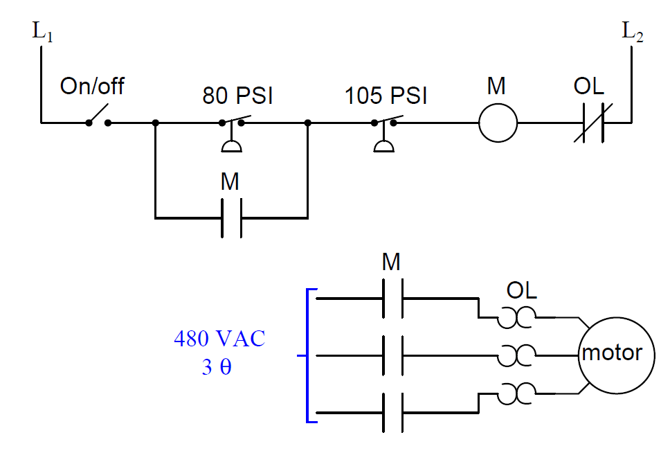
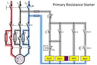
Draw a ladder logic control circuit for the electric motor of an air compressor, controlled by two pressure switches: one switch turns the motor on when the pressure falls to 80 PSI, while the other switch turns the motor off when the pressure rises to 105 PSI:

Draw Electric Motor Ladder Logic

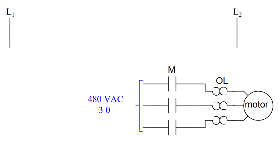
Be sure to include the overload (OL) contact in the 120 volt control circuit (L1 & L2), and include a manual on/off switch as well.

Answer :

Motor ladder Logic

Share Your Answer / Comments

Credits : by Tony R. Kuphaldt – under CC BY 1.0

Don't Miss Our Updates
Be the first to get exclusive content straight to your email.
We promise not to spam you. You can unsubscribe at any time.
Invalid email address
You've successfully subscribed !

Recommended Articles

Identify Level Control Loop Tuning Problems
Calculate Incident Power in Radar Level Measurement
Identify Instrumentation Terms in Water Supply System
How Nuclear Radiation is used to Measure Coke Dust Level?
Response Time Test of RTD and Thermocouple
Switch or Transmitter
Share This Article
Facebook Whatsapp Whatsapp LinkedIn Copy Link
Share
1 Comment
  • HY says:
    April 3, 2022 at 4:11 pm

    auxiliary contact of “M” to be paralleled with ON/OFF switch & contact of “80 PSI” to be “NO contact” .

    Reply

Leave a Reply Cancel reply

Your email address will not be published. Required fields are marked *

Stay Connected

128.3kFollowersLike
69.1kFollowersFollow
208kSubscribersSubscribe
38kFollowersFollow

Categories

Recent Comments

  • William Snyder on Top Non-PLC Certification Courses for Automation Professionals
  • Kamli on Top Free PLC Software
  • Guifty Shimica on Top Non-PLC Certification Courses for Automation Professionals
  • Guifty Shimica on Top Non-PLC Certification Courses for Automation Professionals

Related Articles

Field Instruments Selection Aid

Field Instruments Selection Aid

pressure switch ladder-logic diagram

Draw the appropriate Pressure Switch Symbol ?

Relay Circuit for Hooter with Reset Button

Relay Latching Circuit using Push Button

DCS Vs PLC

Difference between DCS & PLC Systems

PLC program to control pump

Troubleshooting PLC Permissive Inputs

on off valve actuator

How to Select an Actuator for Valve

Problem with Pirani Gauge

Problem with Pirani Gauge

How to Solve Cable Tray Sagging

How to Solve Cable Tray Sagging ?

More Articles

Motor Controls

Design and Implement Motor Control – Electrical Engineering

Simple Loop with Local Indication

Instrument Loop Test Requirements and Operation Procedures

Standard Colors in PLC Automation Systems

Standard Colors in PLC Automation Systems

control of pneumatic systems

Control of Pneumatic Cylinder and Motor

Convert-Linear-%-to-Square-root-%

Formula for Linear % to Square root % conversion

What is Air Circuit Breaker

What is an Air Circuit Breaker? Working Principle & Applications

Vendor Selection in Procurement Service Cycle (For Industrial Projects)

Compliance Table Application (for Procurement Service Cycle)

Pneumatic Level Control Valve

Piping and Instrumentation Drawing (P&ID) Tutorials – Part 3

Follow US
All rights reserved. Reproduction in whole or in part without written permission is prohibited.
Welcome Back!

Sign in to your account

Username or Email Address
Password

Lost your password?