Inst ToolsInst ToolsInst Tools
  • Courses
  • Automation
    • PLC
    • Control System
    • Safety System
    • Communication
    • Fire & Gas System
  • Instrumentation
    • Design
    • Pressure
    • Temperature
    • Flow
    • Level
    • Vibration
    • Analyzer
    • Control Valve
    • Switch
    • Calibration
    • Erection & Commissioning
  • Interview
    • Instrumentation
    • Electrical
    • Electronics
    • Practical
  • Q&A
    • Instrumentation
    • Control System
    • Electrical
    • Electronics
    • Analog Electronics
    • Digital Electronics
    • Power Electronics
    • Microprocessor
  • Request
Search
  • Books
  • Software
  • Projects
  • Process
  • Tools
  • Basics
  • Formula
  • Power Plant
  • Root Cause Analysis
  • Electrical Basics
  • Animation
  • Standards
  • 4-20 mA Course
  • Siemens PLC Course
Reading: Diode Limiters/Clippers Operation
Share
Font ResizerAa
Inst ToolsInst Tools
Font ResizerAa
  • Courses
  • Design
  • PLC
  • Interview
  • Control System
Search
  • Courses
  • Automation
    • PLC
    • Control System
    • Safety System
    • Communication
    • Fire & Gas System
  • Instrumentation
    • Design
    • Pressure
    • Temperature
    • Flow
    • Level
    • Vibration
    • Analyzer
    • Control Valve
    • Switch
    • Calibration
    • Erection & Commissioning
  • Interview
    • Instrumentation
    • Electrical
    • Electronics
    • Practical
  • Q&A
    • Instrumentation
    • Control System
    • Electrical
    • Electronics
    • Analog Electronics
    • Digital Electronics
    • Power Electronics
    • Microprocessor
  • Request
Follow US
All rights reserved. Reproduction in whole or in part without written permission is prohibited.
Inst Tools > Blog > Electronic Devices & Circuits > Diode Limiters/Clippers Operation

Diode Limiters/Clippers Operation

Last updated: October 5, 2016 12:35 pm
Editorial Staff
Electronic Devices & Circuits
No Comments
Share
2 Min Read
SHARE

Diode circuits, called limiters or clippers, are sometimes used to clip off portions of signal voltages above or below certain levels. Another type of diode circuit, called a clamper, is used to add or restore a dc level to an electrical signal.

Diode Limiters

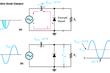
The Below Figure (a) shows a diode positive limiter (also called clipper) that limits or clips the positive part of the input voltage. As the input voltage goes positive, the diode becomes forward-biased and conducts current. Point A is limited to +0.7 V when the input voltage exceeds this value. When the input voltage goes back below 0.7 V, the diode is reverse-biased and appears as an open. The output voltage looks like the negative part of the input voltage, but with a magnitude determined by the voltage divider formed by R1 and the load resistor, RL, as follows:

Diode Limiters Operation

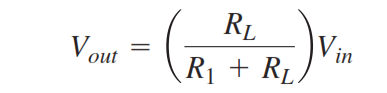
If R1 is small compared to RL, then Vout α Vin.

If the diode is turned around, as in Figure (b), the negative part of the input voltage is clipped off. When the diode is forward-biased during the negative part of the input voltage, point A is held at -0.7 V by the diode drop. When the input voltage goes above -0.7 V, the diode is no longer forward-biased; and a voltage appears across RL proportional to the input voltage.

diode-clipper-principle

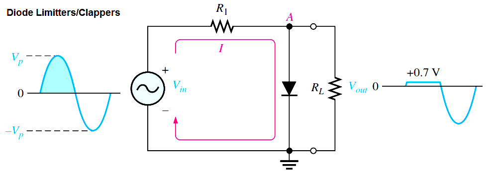
Fig (a) : Limiting of the positive alternation. The diode is forward-biased during the positive alternation (above 0.7 V)  and reverse-biased during the negative alternation.

diode-limiter-principle

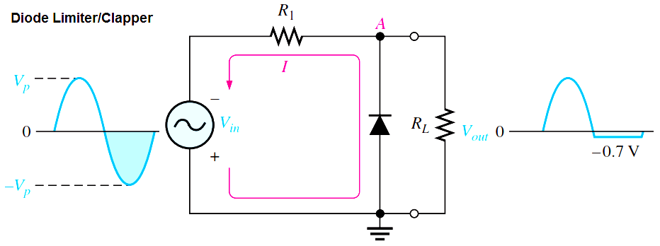
Fig (b) : Limiting of the negative alternation. The diode is forward-biased during the negative alternation (below    – 0.7 V) and reverse-biased during the positive alternation.

Don't Miss Our Updates
Be the first to get exclusive content straight to your email.
We promise not to spam you. You can unsubscribe at any time.
Invalid email address
You've successfully subscribed !

Continue Reading

PMMC Temperature Compensation
Basic Electronics Questions & Answers
Short Notes on Rectifiers & Filters
Resistors Principle & Applications
Capacitively Coupled Multistage Transistor Amplifier
Comparison of Half wave Rectifiers and Full wave Rectifiers
Share This Article
Facebook Whatsapp Whatsapp LinkedIn Copy Link
Share
Leave a Comment

Leave a Reply Cancel reply

Your email address will not be published. Required fields are marked *

Stay Connected

128.3kFollowersLike
69.1kFollowersFollow
210kSubscribersSubscribe
38kFollowersFollow

Categories

Explore More

Transistor as a Switch Working Principle
Testing a Transistor with a Digital Multimeter
JFET Working Animation
Transistor Collector Characteristic Curves
Band Gap for Semiconductor Materials
Ideal Diode Characteristics
Zener Diode Breakdown Characteristics
Positive & Negative Diode Clippers

Keep Learning

Troubleshooting a Biased Transistor

Troubleshooting a Biased Transistor

Capacitor Filter Operation

Capacitor Filter Operation

How a Multi Color LED Works

How a Multi Color LED Works ?

full-wave-bridge-rectifier-with-voltage-regulator

Basics of Voltage Regulators

Types of Resistors

Types of Resistors

Ideal Diode Characteristics Curve

Difference between ideal diode & conventional diode

Permanent magnet moving coil instruments (PMMC)

Permanent Magnet Moving Coil Instruments (PMMC)

how-to-find-resistor-value

Limitations of Resistors

Learn More

Non-Contacting-Radar-Level-Transmitter-Animation

Non Contacting Radar Level Transmitter Animation

Synchronous Generator Salient Pole vs Non Salient Pole

Electrical Machines Questions and Answers

Armature Winding Questions

Instrumentation Inspection and Quality Control Questions

Instrumentation Inspection and Quality Control Questions

What happen When Synchronous Generator loss Excitation

Single Phase Motor Manual Controller

Motor Controllers

Turbo-Compressor Problem

Turbo-Compressor Problem – Root Cause Analysis

PID control block located in fieldbus transmitter

Foundation Fieldbus Device addressing

Menu

  • About
  • Privacy Policy
  • Copyright

Quick Links

  • Learn PLC
  • Helping Hand
  • Part Time Job

YouTube Subscribe

Follow US
All rights reserved. Reproduction in whole or in part without written permission is prohibited.
Welcome Back!

Sign in to your account

Username or Email Address
Password

Lost your password?