Inst ToolsInst ToolsInst Tools
  • Courses
  • Automation
    • PLC
    • Control System
    • Safety System
    • Communication
    • Fire & Gas System
  • Instrumentation
    • Design
    • Pressure
    • Temperature
    • Flow
    • Level
    • Vibration
    • Analyzer
    • Control Valve
    • Switch
    • Calibration
    • Erection & Commissioning
  • Interview
    • Instrumentation
    • Electrical
    • Electronics
    • Practical
  • Q&A
    • Instrumentation
    • Control System
    • Electrical
    • Electronics
    • Analog Electronics
    • Digital Electronics
    • Power Electronics
    • Microprocessor
  • Request
Search
  • Books
  • Software
  • Projects
  • Process
  • Tools
  • Basics
  • Formula
  • Power Plant
  • Root Cause Analysis
  • Electrical Basics
  • Animation
  • Standards
  • 4-20 mA Course
  • Siemens PLC Course
Reading: Difference between ideal diode & conventional diode
Share
Font ResizerAa
Inst ToolsInst Tools
Font ResizerAa
  • Courses
  • Design
  • PLC
  • Interview
  • Control System
Search
  • Courses
  • Automation
    • PLC
    • Control System
    • Safety System
    • Communication
    • Fire & Gas System
  • Instrumentation
    • Design
    • Pressure
    • Temperature
    • Flow
    • Level
    • Vibration
    • Analyzer
    • Control Valve
    • Switch
    • Calibration
    • Erection & Commissioning
  • Interview
    • Instrumentation
    • Electrical
    • Electronics
    • Practical
  • Q&A
    • Instrumentation
    • Control System
    • Electrical
    • Electronics
    • Analog Electronics
    • Digital Electronics
    • Power Electronics
    • Microprocessor
  • Request
Follow US
All rights reserved. Reproduction in whole or in part without written permission is prohibited.
Inst Tools > Blog > Electronic Devices & Circuits > Difference between ideal diode & conventional diode

Difference between ideal diode & conventional diode

Last updated: October 4, 2016 9:36 am
Editorial Staff
Electronic Devices & Circuits
No Comments
Share
5 Min Read
SHARE

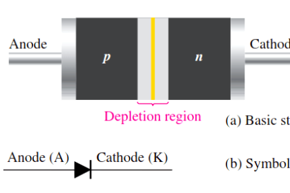
An ideal diode is a diode that acts like a perfect conductor when voltage is applied forward biased and like a perfect insulator when voltage is applied reverse biased.

So when positive voltage is applied across the anode to the cathode, the diode conducts forward current instantly. When voltage is applied in reverse, the diode conducts no current at all.

Ideal Diode Characteristics Curve

Ideal Diode Characteristics Curve


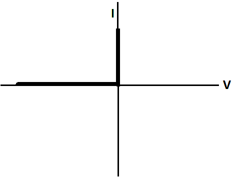
You can see that when the diode receives forward voltage, it instantly conducts an infinite amount of current which it can supply to a circuit. When reverse voltage is fed to the diode, it conducts no current at all, no matter how great this reverse voltage is.

These, again, are ideal circumstances. Diodes actually do not act like this.

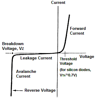
The I-V characteristics curve of a conventional diode would look like this:

Conventional Diode Characteristics Curve

Conventional Diode Characteristics Curve


Below table shows Ideal Diode Vs Conventional Diode

Characteristics Ideal Diode Coventional Diode
Threshold Voltage Ideal diodes do not have a threshold voltage. Once any forward voltage is applied across the diode, it will conduct current instantly across its junctions. Conventional diodes do have a threshold voltage. This is the voltage which must be supplied to the diode for it to conduct any considerable forward current. For silicon diodes, the threshold voltage is approximately 0.7V. For germanium diodes, it is approximately 0.3V. This voltage is needed
so that the electrons of the n junction can have enough push to break the barrier in between and cross over into the p junction. This is how current flows in a diode. Any voltage below the threshold voltage will not be sufficient to push the electrons through from one barrier to the next. You can see this marked on the diode characteristics curve. Before the threshold point, very little current flows across the diode. However,
after the diode receives a voltage above this, it produces considerable current flow.
Forward Current Ideal diodes have infinite forward current when any forward voltage is applied across their terminals. This is because in the ideal condition, the internal resistance of the diode would be 0. The diode would have no internal resistance at all. Since current, I=V/R, an infinite amount of current would be conducted and supplied to a circuit with an ideal diode. Conventional diodes conduct a large current when forward voltage above its threshold voltage is supplied to the diode, but it is still a finite amount of current. Conventional diodes, even though small, still have internal resistance. It is impossible to create any physical component that does not have some internal resistance. The resistance ensures that the current will be finite in nature and cannot be infinite.
Breakdown Voltage Ideal diodes do not have a breakdown voltage. This is because ideal diodes have infinite resistance to reverse voltage. It will not conduct any current at all when voltage is applied in reverse, no matter how great the voltage is. Conventional diodes do have a breakdown voltage. This is the reverse voltage that when applied to the diode will cause the diode junctions to break down and conduct a large amount of current, even though the voltage is applied with incorrect polarity. A diode should not conduct current when voltage is applied the wrong way. However, after a certain point, called the breakdown point, it will give way and conduct.
Reverse (leakage) Current Since an ideal diode does not have a breakdown point,  it never conducts any reverse current, called leakage current. It is a perfect insulator when voltage is applied in reverse. A conventional diode will conduct some leakage current even when reverse voltage is applied, even when the reverse voltage hasn’t reach the breakdown point. After the breakdown voltage is reached, it will conduct a large amount of current, called avalanche current, in reverse. This is because a conventional diode can never be a perfect insulator and will give way if enough reverse voltage is supplied to it.
Don't Miss Our Updates
Be the first to get exclusive content straight to your email.
We promise not to spam you. You can unsubscribe at any time.
Invalid email address
You've successfully subscribed !

Continue Reading

Basics of Ohm’s Law
Dependent Current Source
Full Wave Bridge Rectifier Peak Inverse Voltage
Circuit Elements and Types of Circuits
Basic DC Power Supply Circuit
Half Wave Rectifier Principle
Share This Article
Facebook Whatsapp Whatsapp LinkedIn Copy Link
Share
Leave a Comment

Leave a Reply Cancel reply

Your email address will not be published. Required fields are marked *

Stay Connected

128.3kFollowersLike
69.1kFollowersFollow
210kSubscribersSubscribe
38kFollowersFollow

Categories

Explore More

Half Wave Voltage Doubler using Diodes
Resistors Principle & Applications
Zener Diode Breakdown Characteristics
PMMC Temperature Compensation
Choke Input Filter Operation
Forward Bias & Reverse Bias of a Diode
Band Gap for Semiconductor Materials
Capacitor Filter Working Principle

Keep Learning

Current Divider Rule

Current Divider Rule

Photodiode as Variable Resistance Device

Photodiode as Variable Resistance Device

Reverse Voltage Characteristics of Photo diode

Characteristics of Photo diode

MOSFET VI Characteristics

Power MOSFET

Full Wave Bridge Rectifier Operation

Full Wave Bridge Rectifier Operation

Types of Resistors

Types of Resistors

Reverse Bias Diode Working Animation

Forward Bias & Reverse Bias Diode Working Animation

Diode-testing-with-multimeter

How to Test a Diode using Multimeter

Learn More

Purpose of Stop in a Pressure Measuring Instrument

Purpose of Stop in a Pressure Measuring Instrument

Automation Engineers Interview Questions

Industrial Automation Engineers Interview Questions

Robotic Process Automation

What is Robotic Process Automation? Advantages, Applications

Liapunov’s Stability Analysis

Liapunov’s Stability Criterion – Part I

Hazard Identification and Risk Assessment

Hazard Identification & Risk Assessment (HIRA)

Vibration Sensors Theory

How Vibration sensors Work ?

Relay Symbols

Relay circuits

What is Electrical Panel Door Earth Bonding? Explained

What is Electrical Panel Door Earth Bonding? Explained

Menu

  • About
  • Privacy Policy
  • Copyright

Quick Links

  • Learn PLC
  • Helping Hand
  • Part Time Job

YouTube Subscribe

Follow US
All rights reserved. Reproduction in whole or in part without written permission is prohibited.
Welcome Back!

Sign in to your account

Username or Email Address
Password

Lost your password?