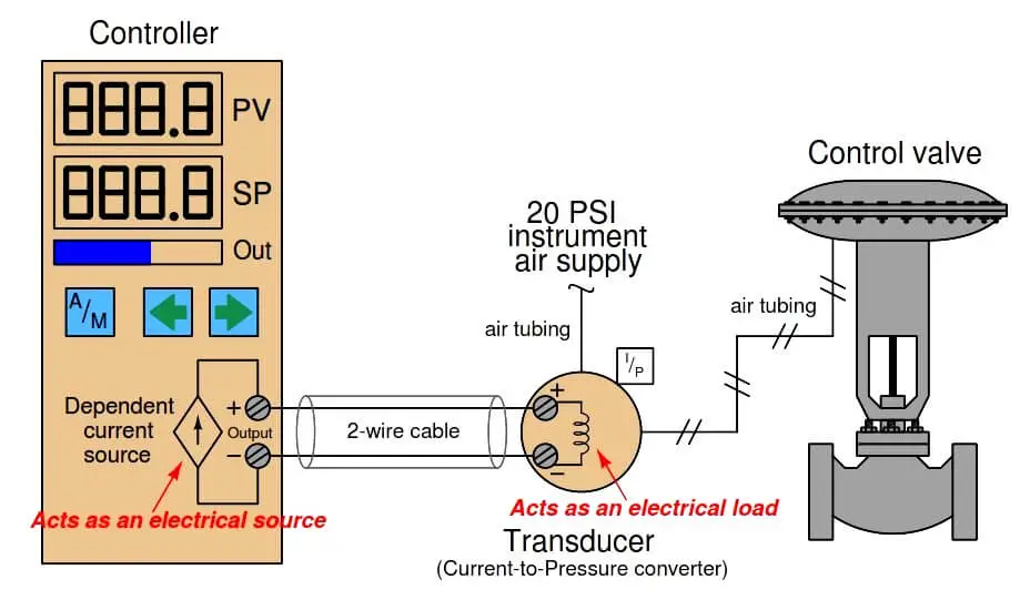
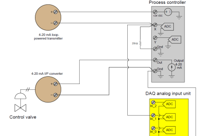
The simplest form of 4-20 mA current loop is the type used to represent the output of a process controller, sending a command signal to a final control element. Here, the controller supplies both the electrical power and signal information to the final control element, which acts as an electrical load. To illustrate, consider the example of a controller sending a 4-20 mA signal to an I/P (current-to-pressure) signal converter, which then pneumatically drives a control valve:
Note : Current to Pressure converter is a part of Valve Positioner
This particular controller has two digital displays, one for process variable (PV) and one for setpoint (SP), with a bargraph for displaying the output value (Out). One pushbutton provides the operator with a way to switch between Automatic and Manual modes (A/M), while two other pushbuttons provide means to decrement and increment either the setpoint value (in Automatic mode) or the Output value (in Manual mode).
Inside the controller, a dependent current source provides the 4-20 mA DC current signal to the I/P transducer. Like all current sources, its purpose is to maintain current in the “loop” circuit regardless of circuit resistance or any external voltage sources. Unlike a constant current source, a “dependent” current source (represented by a diamond shape instead of a circle shape) varies its current value according to some external stimulus. In this case, either the mathematical function of the controller (Automatic mode) or the arbitrary action of the human operator (Manual mode) tells the current source how much DC current it should maintain in the circuit.
For example, if the operator happened to switch the controller into Manual mode and set the output value at 50%, the proper amount of DC current for this signal percentage would be 12 mA (exactly half-way between 4 mA and 20 mA). If everything is working properly, the current in the “loop” circuit to the I/P transducer should remain exactly at 12 mA regardless of slight changes in wire resistance, I/P coil resistance, or anything else: the current source inside the controller will “fight” as hard as it has to in order to maintain this set amount of current. This current, as it flows through the wire coil of the I/P transducer mechanism, creates a magnetic field inside the I/P to actuate the pneumatic mechanism and produce a 9 PSI pressure signal output to the control valve (9 PSI being exactly half-way between 3 PSI and 15 PSI in the 3-15 PSI signal standard range). This should move the control valve to the half-way position.
The details of the controller’s internal current source are not terribly important. Usually, it takes the form of an operational amplifier circuit driven by the voltage output of a DAC (Digital-to-Analog Converter). The DAC converts a binary number (either from the controller’s automatic calculations, or from the human operator’s manual setting) into a small DC voltage, which then commands the opamp circuit to regulate output current at a proportional value.
The scenario is much the same if we replace the I/P and control valve with a variable-speed motor drive. From the controller’s perspective, the only difference it sees is a resistive load instead of an inductive load. The input resistance of the motor drive circuit converts the 4-20 mA signal into an analog voltage signal (typically 1-5 V, but not always). This voltage signal then commands the motor drive circuitry, telling it to modulate the power going to the electric motor in order to drive it at the desired speed:
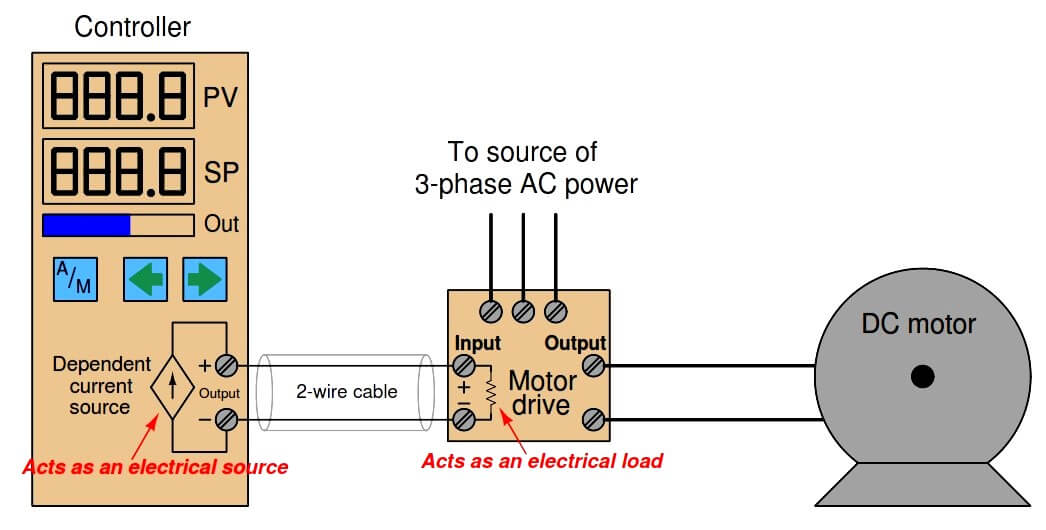
Here, the variable-speed motor drive is a high-power electronic circuit that takes 3-phase AC power in and converts it to DC power at a variable voltage (that voltage level controlled by the 4-20 mA signal from the controller output). Another style of motor “drive” is one that takes in AC power and outputs 3-phase AC power at variable voltage and frequency to power an AC induction motor. This latter style is usually called a variable frequency drive or VFD, but it looks the same to the controller output: a fixed resistive load accepting the 4-20 mA output signal.
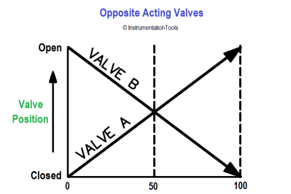
In some process applications the final control element is “reverse-acting” in that a controller output current value of 4 mA tells the FCE to go to its “full” (100%) capacity and a controller output current value of 20 mA commands the FCE to go to its minimum (0%) capacity. Such is the case with an I/P transducer driving an “air-to-close” pneumatic control valve, where the valve’s spring works to push the throttling mechanism open and air pressure on the valve diaphragm works to push the throttling mechanism shut. A practical reason for designing a control system like this is if the dictates of process safety require the valve go wide-open if ever the instrument air supply fails or the 4-20 mA output signal circuit fails.
In such applications, we need to configure the controller in such a way that the output display (digital read-out and/or bargraph) is reverse-indicating so as to avoid confusing any human operator using the controller. Since 4 mA represents a wide-open control valve and 20 mA represents a fully shut control valve, a reverse-indicating controller will display 0% output when the current signal is 20 mA and 100% output when the current signal is 4 mA (i.e. the controller display is a direct representation of control valve stem position, not of the current signal itself ):
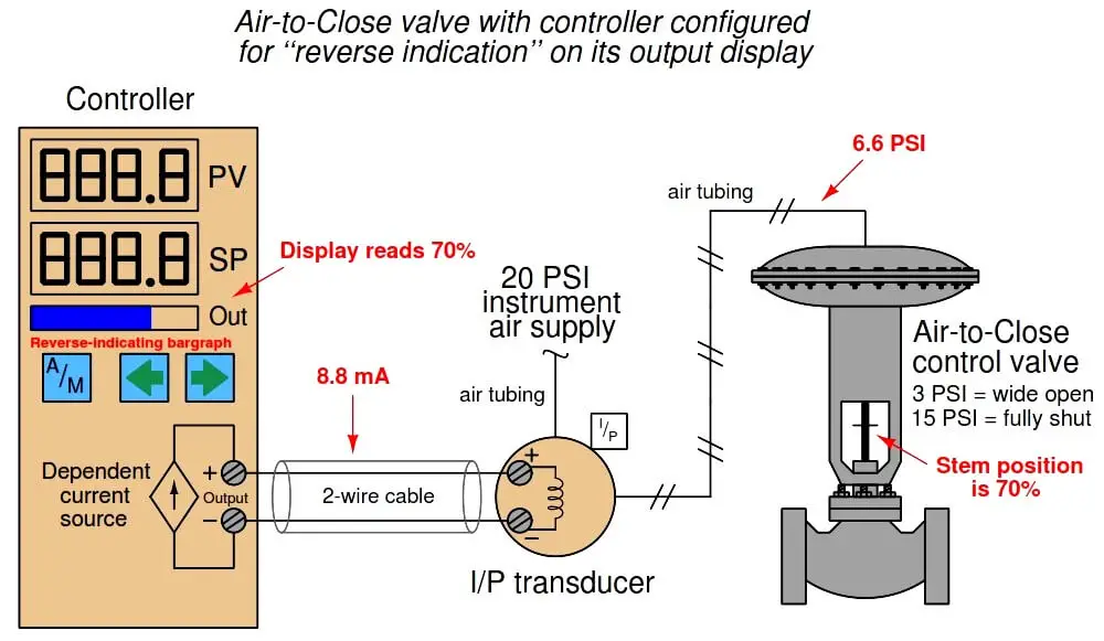
It should be noted that direct or reverse indication on the controller’s faceplate is unrelated to direct or reverse control action of the controller’s algorithm. The former is merely the way in which the output signal is graphically represented to the human operator while the latter is the relationship between the process variable (PV) signal and the controller’s output (MV) signal necessary for negative-feedback control. For the sake of argument, this controller’s automatic action could still be direct (i.e. greater PV signal = greater output signal) even though its output bargraph indication is reverse in order to faithfully show valve stem position to the human operator.
Credits : by Tony R. Kuphaldt – Creative Commons Attribution 4.0 License






Hello everyone,
I’m facing an issue with a gauge pressure transmitter :
when i simulate a pressure in the input of the transmitter,the output on a Hart comminicator is displaying the same value with the DCS but the local displayer of the transmitter is not giving values according the Gauge mounted on the air supply pump.
So can someone help me solve this issue ?
The display may be configured for different units/range.
thanks