Inst ToolsInst ToolsInst Tools
  • Courses
  • Automation
    • PLC
    • Control System
    • Safety System
    • Communication
    • Fire & Gas System
  • Instrumentation
    • Design
    • Pressure
    • Temperature
    • Flow
    • Level
    • Vibration
    • Analyzer
    • Control Valve
    • Switch
    • Calibration
    • Erection & Commissioning
  • Interview
    • Instrumentation
    • Electrical
    • Electronics
    • Practical
  • Q&A
    • Instrumentation
    • Control System
    • Electrical
    • Electronics
    • Analog Electronics
    • Digital Electronics
    • Power Electronics
    • Microprocessor
  • Request
Search
  • Books
  • Software
  • Projects
  • Process
  • Tools
  • Basics
  • Formula
  • Power Plant
  • Root Cause Analysis
  • Electrical Basics
  • Animation
  • Standards
  • 4-20 mA Course
  • Siemens PLC Course
Reading: Dahlander Motor Control Circuit and Power Circuit
Share
Font ResizerAa
Inst ToolsInst Tools
Font ResizerAa
  • Courses
  • Design
  • PLC
  • Interview
  • Control System
Search
  • Courses
  • Automation
    • PLC
    • Control System
    • Safety System
    • Communication
    • Fire & Gas System
  • Instrumentation
    • Design
    • Pressure
    • Temperature
    • Flow
    • Level
    • Vibration
    • Analyzer
    • Control Valve
    • Switch
    • Calibration
    • Erection & Commissioning
  • Interview
    • Instrumentation
    • Electrical
    • Electronics
    • Practical
  • Q&A
    • Instrumentation
    • Control System
    • Electrical
    • Electronics
    • Analog Electronics
    • Digital Electronics
    • Power Electronics
    • Microprocessor
  • Request
Follow US
All rights reserved. Reproduction in whole or in part without written permission is prohibited.
Inst Tools > Blog > Electrical Basics > Dahlander Motor Control Circuit and Power Circuit

Dahlander Motor Control Circuit and Power Circuit

In this article, you will learn the dahlander motor control circuit and power circuit diagrams and their explanation.

Last updated: September 28, 2022 2:22 pm
Hussien Ghareb
Electrical Basics
1 Comment
Share
4 Min Read
SHARE

Welcome back, in the last article “The Idea Behind Dahlander Motors” we were curious about the need for Dahlander motors and we learned the main idea beyond these motors also when and how to use these types of induction motors.

Contents
Power Circuit of a Dahlander MotorControl Circuit of the Dahlander Motor

Today we are going more practically by discussing the dahlander motor control circuit and How it could be performed using the “classic control circuit design”.

Dahlander Motor

Power Circuit of a Dahlander Motor

As we discussed before, the speed control of the normal Induction motors is not simple and can be made by adjusting two different factors (Frequency of the power source, Number of poles in the motor winding).

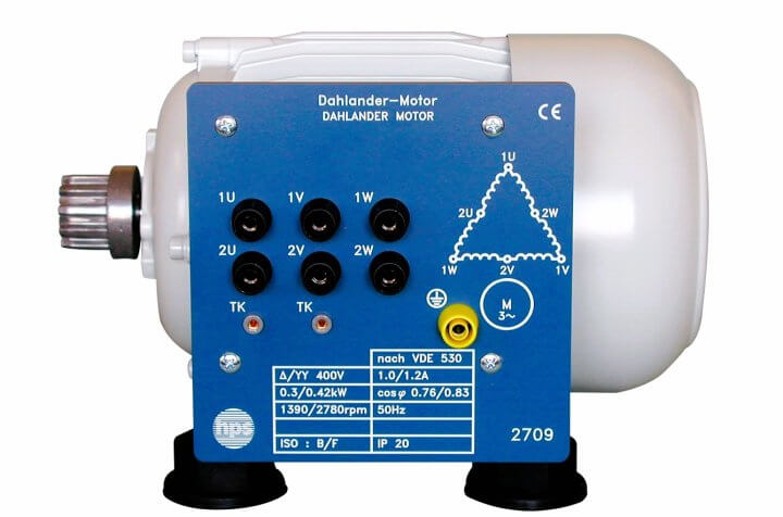
Dahlander motor is nothing more than a two-speed induction motor and we can handle these two speeds by switching the configuration of the electrical windings, indirectly adding or removing poles, and thus varying the rotor speed.

For further explanation please find the previous post (“Dahlander Motors”)

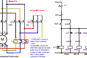
Here in below figure we can see the power circuit diagram for a Dahlander motor, the circuit consists of:

Protection Element: we can see (F1) that represents the protection fuse for the power circuit this element could be replaced by a suitable circuit breaker or motor overload, it depends on your application and the desired response of your protection element.

Dahlander Motor Control Circuit

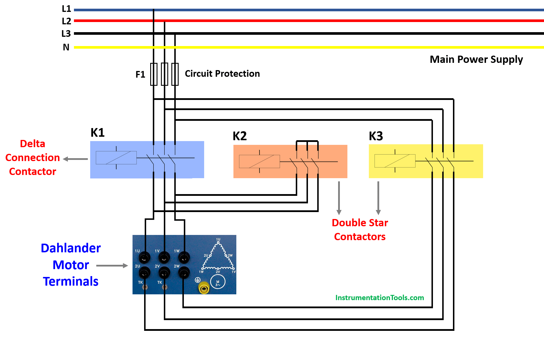
Delta connection contactor (K1):

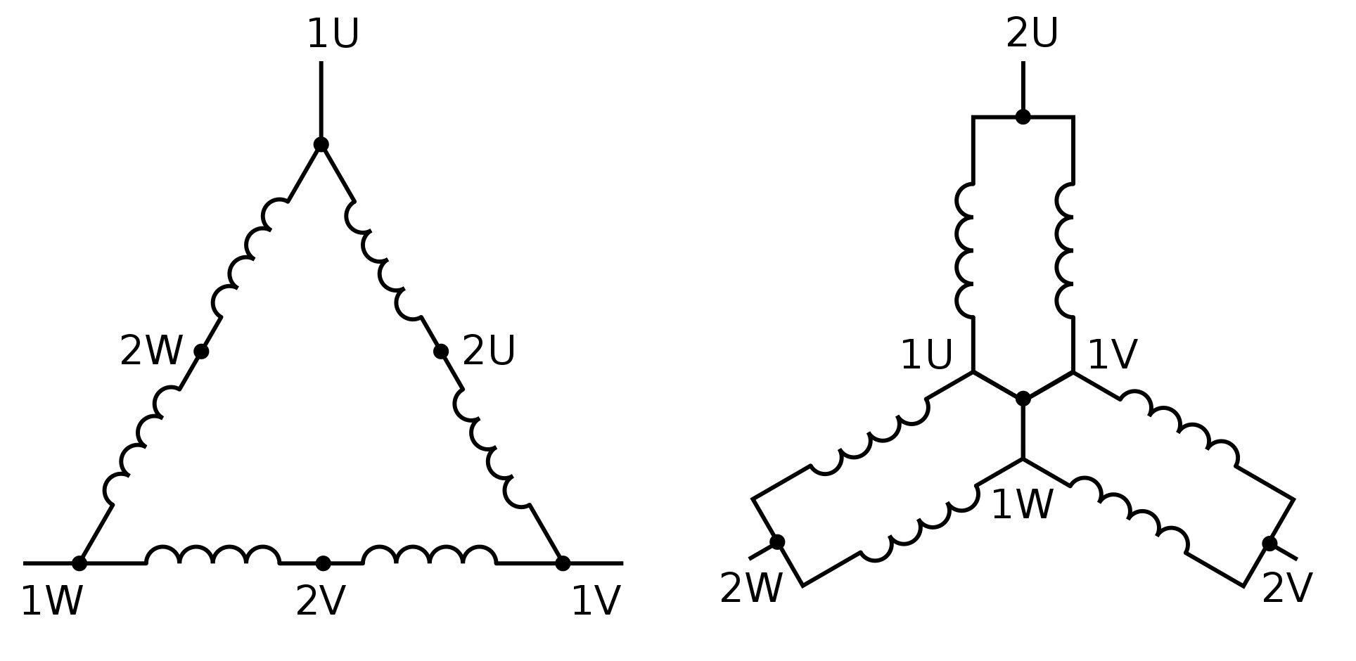
This contactor is responsible for connecting the internal coils of the dahlander motor as a delta connection to set the lower speed. The respective image is shown on the left side of the below image.

The power supply phases should be connected at [U1, W1, V1] using K1 contactor.

Double star contactors

Double star contactors (K2 – K3):

These two contactors are responsible for connecting the internal coils of the dahlander motor as a double star connection to set the highest speed. The respective image is shown on the right side of the above image.

The power supply phases should be connected at [U2, W2, V2] using K3 contactor, and [U1, W1, V1] should be shorted using K2 contactor.

Control Circuit of the Dahlander Motor

Here we can see the below Figure the control circuit of a Dahlander Motor.

Control Circuit of the Dahlander Motor

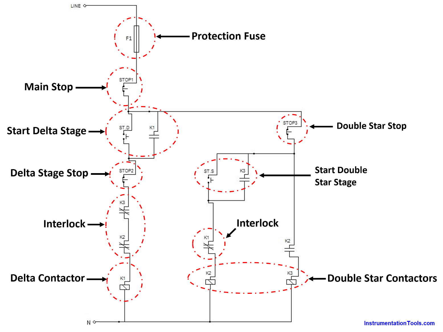
This motor is controlled by three stop (NC) push buttons, (STOP1) to stop the two stages of the motor, (STOP2) to stop the delta stage, and (STOP3) to stop the double star stage.

Also, there are two start (NO) push button, one for the delta stage and the other for the Double star stage.

There must be an electrical interlock between the two stages to prevent any hazards (like phases shortage) when you are switching between the two stages.

If you liked this article, then please subscribe to our YouTube Channel for Instrumentation, Electrical, PLC, and SCADA video tutorials.

You can also follow us on Facebook and Twitter to receive daily updates.

Read Next:

DOL Starter Circuit Diagrams
Earth Leakage Circuit Breaker
Star Delta Starter Circuit Diagrams
Control Two Motors after Time Delay
Thermal Protection Relay for Motors

Don't Miss Our Updates
Be the first to get exclusive content straight to your email.
We promise not to spam you. You can unsubscribe at any time.
Invalid email address
You've successfully subscribed !

Continue Reading

Motor Maintenance, Troubles, Regular Checks, Performance
How to Size a Cable for Industrial AC Motors?
What are Switchgear Interlocks?
What is insulation? How to Choose the Insulation Material?
Motor Classic Control Circuits using Single Push button
What are HP and LP Switches in HVAC?
Share This Article
Facebook Whatsapp Whatsapp LinkedIn Copy Link
Share
1 Comment
  • Gratius says:
    February 12, 2023 at 9:32 pm

    my name is Uwiragiye From Rwanda how can i get a dahlander motor

    Reply

Leave a Reply Cancel reply

Your email address will not be published. Required fields are marked *

Stay Connected

128.3kFollowersLike
69.1kFollowersFollow
210kSubscribersSubscribe
38kFollowersFollow

Categories

Explore More

Partial Discharge in Power Lines and its Detection through Sensors
Electrical Terminology
Motor VFD Drive features
Why Circuit Breakers Don’t Protect People?
MCB vs Fuse Questions and Answers
Electric Motor Winding Temperature Sensors
What is a Power Transformer? – Components and Types
Difference Between RCCB and MCCB

Keep Learning

LCS Configuration equipped with LOTO Facility

Motor Control Signal Interface

VFD Commissioning and Testing Procedure

VFD Commissioning and Testing Procedure (Variable Frequency Drive)

Difference Between Metering CT and Protection CT

Difference Between Metering CT and Protection CT

Types of MCB

Types of MCB

Semiconductor Fuse

What is a Semiconductor Fuse?

Lead Acid Battery Operation

How does a Lead Acid Battery Work?

Rotary Encoder

Rotary Encoder Interview Questions and Answers

Why is HV Testing important in Electrical Panels?

Why is HV Testing important in Electrical Panels?

Learn More

Digital Electronics Multiple Choice Questions

Parity Generators Objective Questions

Classification of HVAC chillers

Classification of HVAC Chillers

Induction Motor Operating Characteristics

PLC datasheet

How to Read the PLC Datasheet? – Important Notes About PLC

Why are Impulse Lines often Installed in a Sloping Manner (Angle)

Why are Impulse Lines often Installed in a Sloping Manner?

Vibration Sensor

Vibration Probes Questions and Answers

interview-questions-and-answers-on-natural-gas

Oil and Gas Interview Questions Answers

Level Measurement Objective Questions

Level and Density Measurement Objective Questions

Menu

  • About
  • Privacy Policy
  • Copyright

Quick Links

  • Learn PLC
  • Helping Hand
  • Part Time Job

YouTube Subscribe

Follow US
All rights reserved. Reproduction in whole or in part without written permission is prohibited.
Welcome Back!

Sign in to your account

Username or Email Address
Password

Lost your password?