 |
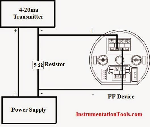
| Terminal Diagram with 4-20 mA Conversion to 20-100 mV |
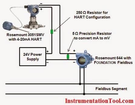
| Wiring diagram for Rosemount 3051SMV converted into FOUNDATION Fieldbus signal |
ROSEMOUNT 644 CONFIGURATION
Configuration of the 644 can be performed using a Handheld Field Communicator or AMS Device Manager. Configure the sensor type and device units to “mV.” Configure the AI block of the 644 as follows:
1. Set the MODE_BLK.TARGET to OOS
2. Set CHANNEL to the transducer block configured for the analog input
3. Set XD_SCALE.EU_0 to 20 Set XD_SCALE.EU100 to 100
Set XD_SCALE.ENGUNITS to mV
4. Set OUT_SCALE to match the desired scale and units for the connected analog transmitter.
5. Flow Example: 0-200 gpm OUT_SCALE.EU_0 = 0 OUT_SCALE.EU_100 = 200 OUT_SCALE.ENGUNITS = gpm
6. Set L_TYPE to INDIRECT
7. Set the MODE_BLK.TARGET to AUTO
Also Read: Foundation Fieldbus Principles
Lube oil consoles of rotary equipment packages in industrial process plants are usually equipped with…
Rotating equipment packages such as pumps, compressors, turbines need the lube oil consoles for their…
This article explains how to blink lights in ladder logic with a detailed explanation video…
In this article, a simple example will teach you the conversion from Boolean algebra to…
In this article, you will learn the PLC cooking timer example for kitchen automation using…
Learn an example PLC program to control a pump based on level sensors using ladder…
View Comments
well i really dont know how to convert hart to FF but you solved my problem.
Thanks for the description.
Is there any device to convert FF signal to 4 to 20 ma or 1 To 5 V DC
In the 2nd figure, you have connected 5ohm resistor in parallel not in series, but in the first figure its connected in series.
Hi, in both figures the 5 Ohm precision resistor is connected in parallel of the Fieldbus Foundation (FF) device and in series within the Hart loop.