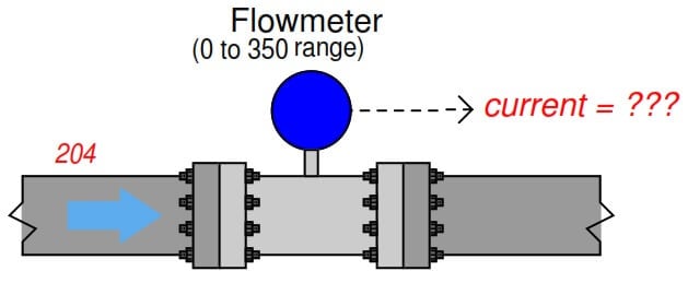
A flow transmitter ranges from 0 to 350 GPM with 4 to 20 mA output, direct-responding. Calculate the current signal value at a flow rate of 204 GPM.
We are solving this problem using the standard 4-20mA Conversion Formula. Click here for the formula
One way we could solve for the amount of signal current is to convert the flow value of 204.
GPM into a ratio of the flowmeter’s full-flow value, then apply the same formula we used in the previous example relating percentage to milliamps.
Converting the flow rate into a “per unit” ratio is a matter of simple division since the flow measurement range is zero-based:
Therefore, the transmitter should output a PV signal of 13.3 mA at a flow rate of 204 GPM.
An alternative approach is to set up a linear equation specifically for this flowmeter given its measurement range (0 to 350 GPM) and output signal range (4 to 20 mA).
We will begin this process by sketching a simple graph relating flow rate to current:
Therefore, the transmitter should output a PV signal of 13.3 mA at a flow rate of 204 GPM.
We can also solve the problem using a direct formula. Click here for the formula
If you liked this article, then please subscribe to our YouTube Channel for Instrumentation, Electrical, PLC, and SCADA video tutorials.
You can also follow us on Facebook and Twitter to receive daily updates.
Read Next:
Design a control system for automatic door lock with delay using PLC programming and motion…
In the PLC emergency stop example program, when the emergency button is pressed, the elevator…
This article is about controlling the double-acting pneumatic cylinder movement control with a timer circuit.
In this article, we will review the main responsibility scopes of the instrumentation and electrical…
Learn the daily alarm PLC program using real-time clock instruction as per the required timings…
A Real-Time Clock accurately tracks time from seconds to years and stores the data in…


View Comments
Also Another Simple way to calculate:
Signal = 4 - 20 mA..
So Signal varies between 16 mA
So Each gallon tends to have (16/350)= 0.046 mA
So 204 Gallon will make (0.0457 * 204) = 9.33 mA
Hence Output signal will be 4 mA + 9.33 mA = 13.33 mA
how calibrate a ff type flow transmitter ABB 2600T range is 53.39mbar and out showing 5000m3/H how calculate plz gv reply on transmitter showing 53.39 m baar and on data sheet showing calibration range 5000 m3/hm confuse