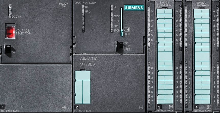
Upload Option Disabled in Siemens PLC
How to upload the PLC ladder logic program in Siemens PLC if the upload option (icon) is disabled? Let's learn with our tutorial. This article is about uploading the PLC…
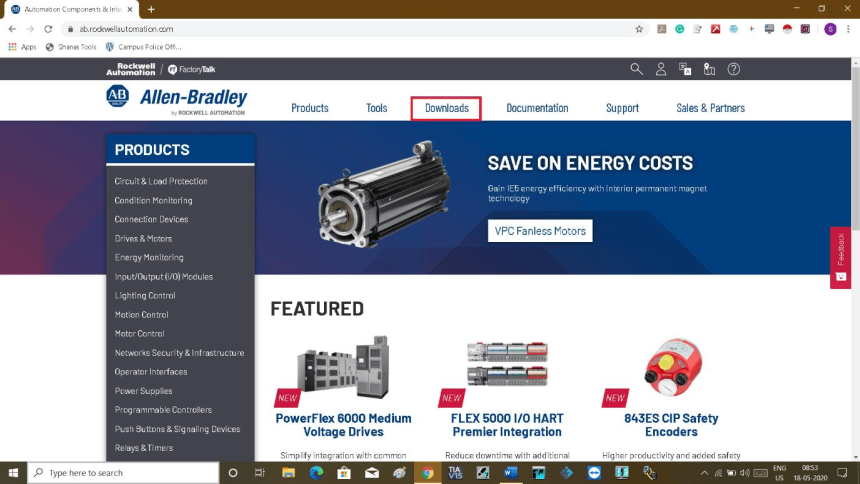
Download Allen Bradley RSLogix PLC Software
As we know that many people do plc training to enhance their programming skills but they only can able to do at the training centre. When they go back home,…
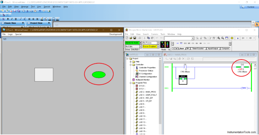
Communication between InTouch Scada and Allen Bradley PLC
This article is about communication between InTouch SCADA and Allen Bradley PLC with a ladder logic example with screenshots. InTouch Scada and Allen Bradley PLC Do follow the below steps…
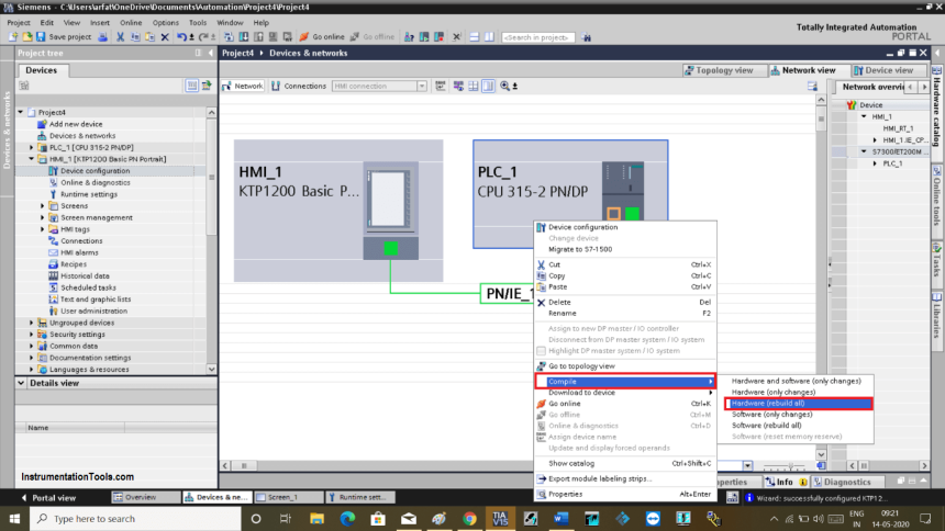
Configuration of Input and Output Tags in Siemens Scada and PLC
This article is about the configuration of input and output tags while establishing communication between SCADA and PLC using Siemens TIA portal. Configuration of Input and Output Tags As there…
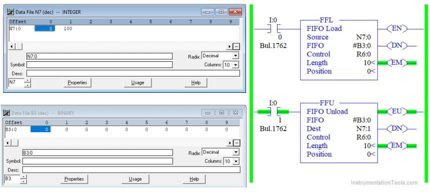
FIFO Instruction in Allen Bradley PLC Programming
What Is FIFO in Rockwell PLC Programming? FIFO is a special programming instruction that can be used in the applications that require to store the sequence of data in order…
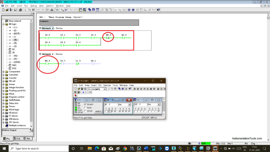
What is Midline Instruction in Siemens PLC?
This article is about the use of midline instruction in the siemens PLC. Many times, in industrial PLC programming we have to use the same rung condition with additional input.…
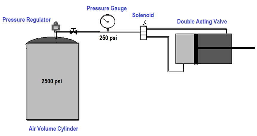
Air Cylinder Consumption Calculation for Control Valves
The single-acting spring return cylinder: These are just like the standard single-acting cylinders with the exception that they have a spring inside of them. At the completion of the power…
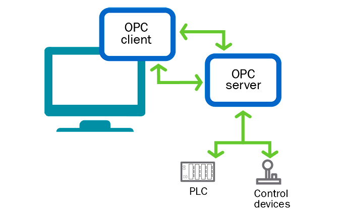
OPC in Old PLC Systems
OPC (Object Linking and Embedding for process control) was released in 1996 by the OPC Foundation and was soon adopted for the interoperability of industrial systems. The name was later…
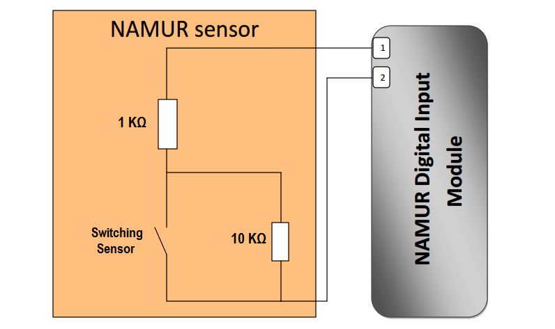
What is Namur Digital Input Card?
What is Namur digital input card? And what it is used for? If you open the hardware configuration in the SIMATIC manager platform for Siemens PLC programming software and want…
Communication between Wincc and Tia Portal
This article is about communication between WinCC and TIA portal using simple programming examples and screenshots. Wincc and Tia Portal Step 1: Open TIA PORTAL. Create a new project. Configure…
