Explain how the following annunciator circuit works:
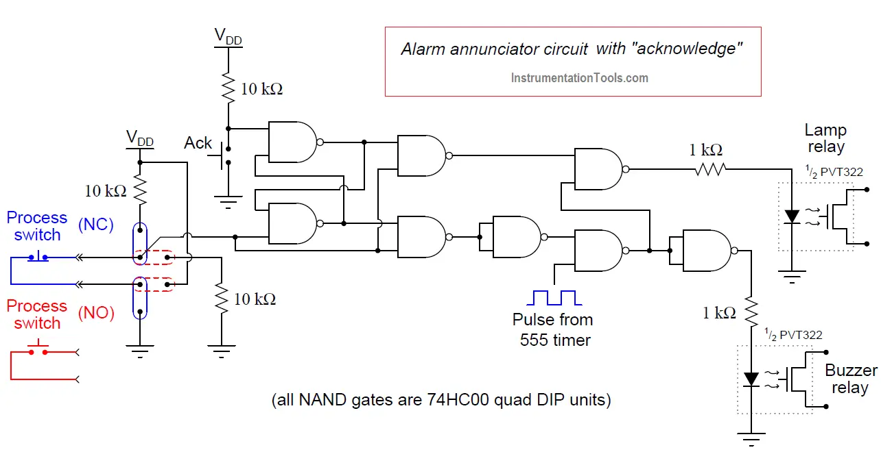
Note the jumper options shown in the diagram: one set of jumper positions configures the alarm for a process switch that alarms when its contacts open, and the other positions configure the alarm for a process switch that alarms when its contacts close.
In either case, the circuit is designed to indicate an alarm status when the line going in to the lower-left NAND gate goes high.
The first two (left-most) NAND gates form an active-low S-R latch circuit. That is, a “low” state on the upper input (from the acknowledge switch) sets the S-R latch so that the upper NAND gate outputs a high signal, and a “low” state on the lower input (process switch returning to a non-alarm condition) “resets” the S-R latch so that the lower NAND gate outputs a high signal.
Thus, the purpose of the S-R latch is to remember the “acknowledged” status of the alarm point. Actuating the “Ack” switch sets the latch and acknowledges the alarm.
Having the process switch return to a normal (non-alarm) status resets the latch and prepares the circuit for full alert (flashing light and pulsing buzzer) for the next alarm state.
Credits: Tony R. Kuphaldt
Design a control system for automatic door lock with delay using PLC programming and motion…
In the PLC emergency stop example program, when the emergency button is pressed, the elevator…
This article is about controlling the double-acting pneumatic cylinder movement control with a timer circuit.
In this article, we will review the main responsibility scopes of the instrumentation and electrical…
Learn the daily alarm PLC program using real-time clock instruction as per the required timings…
A Real-Time Clock accurately tracks time from seconds to years and stores the data in…
