Inst ToolsInst ToolsInst Tools
  • Courses
  • Automation
    • PLC
    • Control System
    • Safety System
    • Communication
    • Fire & Gas System
  • Instrumentation
    • Design
    • Pressure
    • Temperature
    • Flow
    • Level
    • Vibration
    • Analyzer
    • Control Valve
    • Switch
    • Calibration
    • Erection & Commissioning
  • Interview
    • Instrumentation
    • Electrical
    • Electronics
    • Practical
  • Q&A
    • Instrumentation
    • Control System
    • Electrical
    • Electronics
    • Analog Electronics
    • Digital Electronics
    • Power Electronics
    • Microprocessor
  • Request
Search
  • Books
  • Software
  • Projects
  • Process
  • Tools
  • Basics
  • Formula
  • Power Plant
  • Root Cause Analysis
  • Electrical Basics
  • Animation
  • Standards
  • 4-20 mA Course
  • Siemens PLC Course
Reading: What is Electrical Panel Door Earth Bonding? Explained
Share
Notification Show More
Font ResizerAa
Inst ToolsInst Tools
Font ResizerAa
  • Courses
  • Design
  • PLC
  • Interview
  • Control System
Search
  • Courses
  • Automation
    • PLC
    • Control System
    • Safety System
    • Communication
    • Fire & Gas System
  • Instrumentation
    • Design
    • Pressure
    • Temperature
    • Flow
    • Level
    • Vibration
    • Analyzer
    • Control Valve
    • Switch
    • Calibration
    • Erection & Commissioning
  • Interview
    • Instrumentation
    • Electrical
    • Electronics
    • Practical
  • Q&A
    • Instrumentation
    • Control System
    • Electrical
    • Electronics
    • Analog Electronics
    • Digital Electronics
    • Power Electronics
    • Microprocessor
  • Request
Follow US
All rights reserved. Reproduction in whole or in part without written permission is prohibited.
Inst Tools > Blog > Electrical Basics > What is Electrical Panel Door Earth Bonding? Explained

What is Electrical Panel Door Earth Bonding? Explained

Learn about Electrical Panel Door Earth Bonding to prevent electrical shocks and safely protect your system from hazards.

Last updated: June 6, 2025 11:21 am
Viral Nagda
Electrical Basics
No Comments
Share
6 Min Read
SHARE

Earthing is a very important part of electrical systems. Without them, it is not possible to safely protect the system from getting an electrical shock or other short-circuit hazards. Often, people think that touching a non-current-carrying part will not give them an electrical shock. But that is not true. Leakage current travels through any part of the panel if earthing is not present. And it can reside in these non-current paths. So if anyone touches that, they can get a shock too. One of the most related non-current parts is a panel door or enclosure body. In this post, we will see the concept of the panel door earth bonding procedure.

Contents
Why is earthing important in electrical panels?Difference between earthing, grounding, and bondingElectrical Panel Door Earth Bonding

Why is earthing important in electrical panels?

Any electrical panel has leakage current or residual current flowing due to broken wires, improper wiring, or a faulty component. Due to this, the current flows in the parts that are not alive in nature, like metal bodies. If anyone gets in contact with this current by touching that part, then they may get an electrical shock. For this reason, there must be some means to discharge this leakage current safely to a certain path. This is done by earthing.

All the conductive points have a dedicated point for earthing; and all the non conductor paths can be fitted with a screw point for earthing connection. From that point, wires are drawn to the main earth pit dug outside the building premises. Due to this, any leakage current in the panel flows into the earth pit, thus providing a safe passage for the residual current. Now, even if anyone touches the part, then he will not get an electrical shock. The earth conductor or wire must have low resistance to allow the flow of current. Not even non-live parts, but even the live components are protected from leakage current flowing in its path.

Difference between earthing, grounding, and bonding

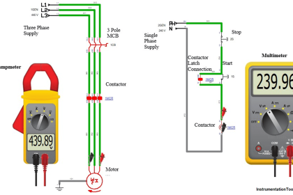
Now, we must understand the three terms before discussing our topic: earthing, grounding, and bonding. Refer to the image below for more understanding. In the image, you see a circuit breaker. The circuit breaker is a live component that controls the flow of current through it and trips the circuit in case of any fault. The circuit breaker will have a point for an earthing connection. The panel in which the breaker is mounted too has a screw point for connecting earthing wire. Now, the door is a metallic part, making it easy to conduct current. The door must thus be connected to the panel earth point, to make it available to the ground path. This is done by joining a metallic conductor or wire; the process is called bonding.

What is Electrical Panel Door Earth Bonding? Explained

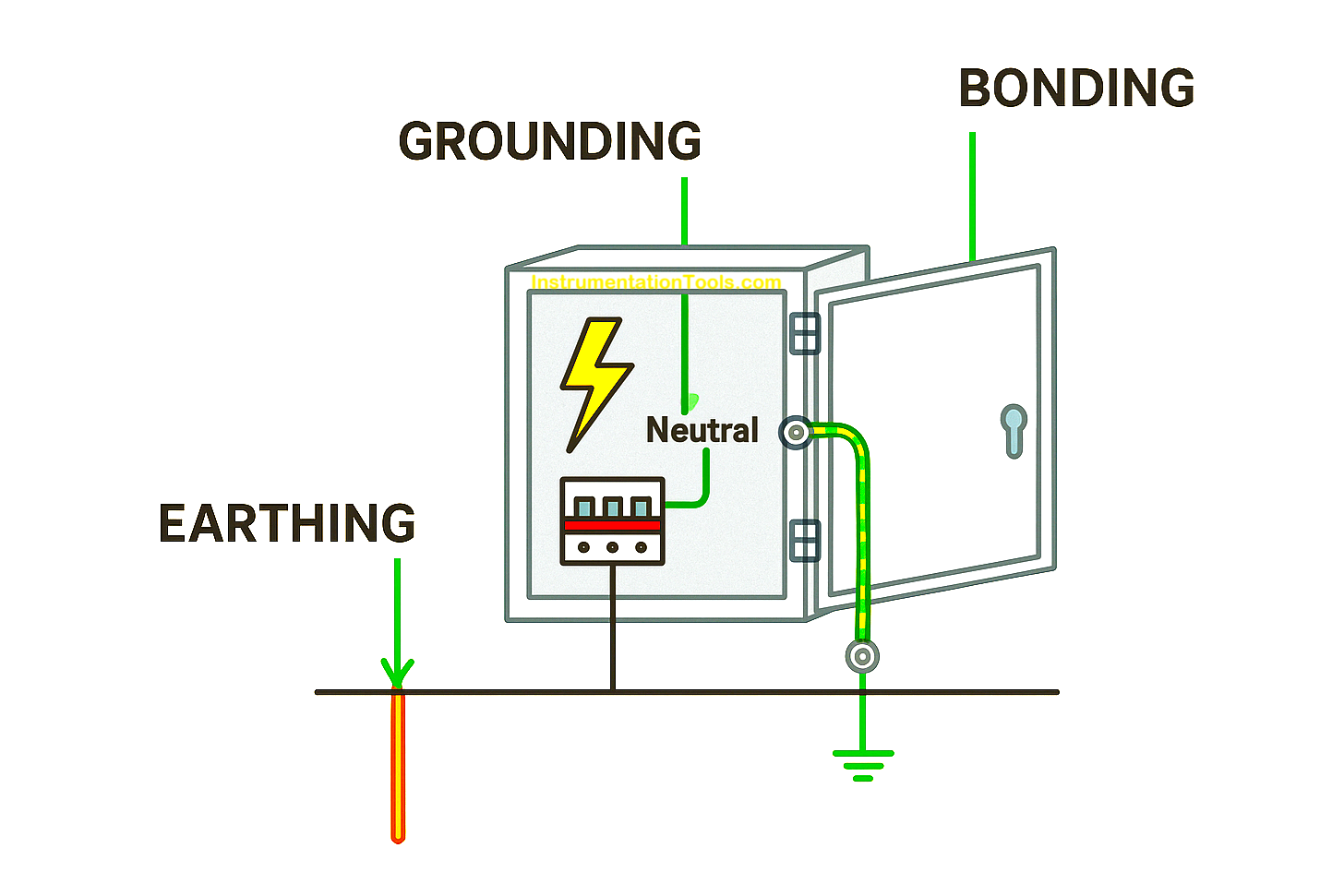
So, basically, earthing and grounding are the same terms and concepts, as both connect to the earth pit. But to be precise, according to IEC standards, when you connect a non-current-carrying part like a panel body to the earth, it is called earthing. When you connect a live, current-carrying part, like the breaker to the earth, it is called grounding. When you connect two parts, either current-carrying or non-current-carrying, with each other, so that both of them are at the same earth potential, then it is called bonding. All the terms are related to each other, with only a slight difference between them. Bonding is just a way to join two parts, and is not actually connected directly to the earth point. This ensures that all the points are at the same earth potential.

Electrical Panel Door Earth Bonding

Now that we have understood what earth bonding is, let us see the practical steps on how to implement it on an electrical panel door:

  1. Power off the system. Now, first ensure that your panel body is grounded to the earth. It will be done either on its outer body having a screw terminal for connection, or connecting it internally to the instrument earth bar.
  2. Once done, you then connect the screw point on the door to the panel body through a metallic wire conductor. It must be a standard yellow-green striped color.
  3. When wires, first check that your door moves freely and is not held by the wire. The wire should be neither too tight nor too loose. If this is free to move, then it means your panel door has now been joined with the panel body earth, thus bringing it to the same potential level.
  4. Check the resistance of the wire (between the door and panel body); it should be less than 1V, or the same as the other point’s resistance in the panel. Once done, this will now ensure that your bonding has complied with standards and is ready to use.

Now, when you touch the panel door, you will not get an electrical shock. In this way, we saw the concept of the panel door earth bonding procedure.

Read Next:

  • Electrical Drives Speed Control Application
  • VFD Simulator Free Download Software
  • Comparison of Electrical Protection Relays
  • Testing of Bonding and Grounding Systems
  • Importance of a Grounding System

Don't Miss Our Updates
Be the first to get exclusive content straight to your email.
We promise not to spam you. You can unsubscribe at any time.
Invalid email address
You've successfully subscribed !

Continue Reading

Siemens Standard Drives Application Handbook (PDF)
Difference Between MCB and MCCB
VFD Pros and Cons – Variable Frequency Drives
What is Power Cable? Types of Power Cables
Design and Implement Motor Control – Electrical Engineering
Difference between UPS and Stabilizer?
Share This Article
Facebook Whatsapp Whatsapp LinkedIn Copy Link
Share
Leave a Comment

Leave a Reply Cancel reply

Your email address will not be published. Required fields are marked *

Stay Connected

128.3kFollowersLike
69.1kFollowersFollow
210kSubscribersSubscribe
38kFollowersFollow

Categories

Explore More

Polarization Index (PI) Test and DA Test
Basics of Electricity Rates
What is the LBB Protection Relay? (Local Breaker Backup)
What is Electrical Conduit? Types, Advantages, Disadvantages
Technical Specification for Uninterrupted Power Supply (UPS) System
Types of Electrical Wiring
How to Read and Understand an Electrical Single Line Diagram?
Basic Electrical Engineering Questions & Answers

Keep Learning

VFD Commissioning and Testing Procedure

VFD Commissioning and Testing Procedure (Variable Frequency Drive)

VFD Block Diagram

What is a VFD? – Theory, Advantages, Disadvantages

Top 100 Power Systems Projects

Top 100 Power Systems Projects – Electrical Engineering

Electrical Voltage and current Signals

Electrical Voltage and current Signals

Why is Motor Control Required in Control Systems

Why is Motor Control Required in Control Systems?

Applications of Electrical Conduit System

What is an Electrical Conduit? – Types – How to Choose?

Group of Induction Motors

How to Operate a Group of Induction Motors using PLC Logic?

Top 10 Common Mistakes on Electrical Systems

Top 10 Common Mistakes on Electrical Systems

Learn More

PLC Based Metro Automation Project

PLC based Metro Automation Project

Group of Induction Motors

How to Operate a Group of Induction Motors using PLC Logic?

Instrumentation Transmitter

Instrumentation Common Measurement Issues

conductivity transmitter

Conductivity Transmitter Calibration Procedure

Chemical Battery

Batteries

Types of Pressure

Types of Pressure – Instrument Questions and Answers

Conditional Jump instruction

Jump Instruction in Siemens Tia Portal

Electronic Symbols List

Electronic Symbols

Menu

  • About
  • Privacy Policy
  • Copyright

Quick Links

  • Learn PLC
  • Helping Hand
  • Part Time Job

YouTube Subscribe

Follow US
All rights reserved. Reproduction in whole or in part without written permission is prohibited.
Welcome Back!

Sign in to your account

Username or Email Address
Password

Lost your password?