HART ADDRESSING
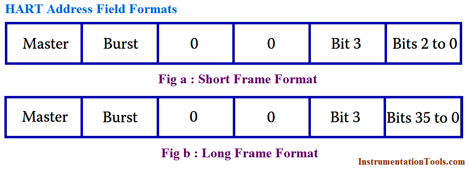
HART addressing is of two types: polling address and unique identifier. Polling address is single byte and is also known as “short address.” Unique identifier is of 5 bytes and also called “long address.”
The address field formats for the short and the long frames are shown in Figure. One bit of the short address distinguishes the two masters, while another bit indicates burst mode telegrams. The remaining four bits distinguish the field devices (from 0 to 15)—0 for single-unit mode and 1–15 corresponds to multidrop mode. The polling address format is used with old HART devices that do not support the long address format.
The 5-byte unique identifier is a hardware address that consists of 1-byte manufacturer code, 1-byte device type code, and a 3-byte sequential number. This 5-byte ID is unique for each device. HCF administers the manufacturer code, which eliminates the possibility of address duplication of any two HART devices. The master uses this unique long address to communicate with the slaves.
In single mode, the master polls address 0 to get the unique slave ID. In multidrop mode, the master checks all the polling addresses 0 to 15 to check device presence. The master then presents a list of live devices on the network. A user can alternatively enter the tag of the intended device and the master will broadcast the same.
The slave with the unique ID and the tag responds against this query from the master. The polling address, in conjunction with he unique ID, indicates whether the message exchange is from a primary or secondary master and whether the slave is in the burst mode or not.
ARBITRATION
Arbitration ensures proper message transmission between master and the slave devices. There can be either master–slave or burst mode. In the former, it is the master that initiates message transmissions, by requesting the slave device. The slave device, in turn, responds only to the query from the master. A slave in the master–slave mode of operation can never initiate communication.
There can be two masters on the network—a primary master and a secondary master—which may typically be a handheld terminal. Arbitration between the two masters is based on timing.
The slave burst mode, like the master–slave mode, is initiated by a command from the master. In this, burst mode responses are generated by the requested slave without request frames from the master. Data is updated at a faster rate since the slave goes on transmitting without a request from the master.
A frame, either from a master or a slave, is transmitted only after ensuring that no transmission is taking place on the network at that point of time. It is the responsibility of the timer to allow access to the network to the primary masters, secondary masters, slaves, or slaves in burst mode. Both masters have equal priority in getting access to the bus. In case both masters have to repetitively access the bus, they would do so alternately. Burst mode slaves wait longer than the masters to transmit, allowing the masters to control such slaves—either to continue or abort the burst mode.
COMMUNICATION MODES
Communication employing HART protocol can either be master–slave or burst mode. In the former mode, communication is initiated by the master. A HART communication loop may have two masters: primary and secondary. The master is typically a system host—may be a distributed control system, a PLC, or a personal computer. The secondary master can be a handheld configuration tool (i.e., a handheld terminal) used for occasional configurations of different process parameters.
A slave may be a transmitter or a valve positioner. Burst mode configuration provides the master with certain information on a continuous basis, until told to stop. It provides for a faster communication (about three to four data updates per second) than the master–slave mode and is used in single-slave configuration.
HART NETWORKS
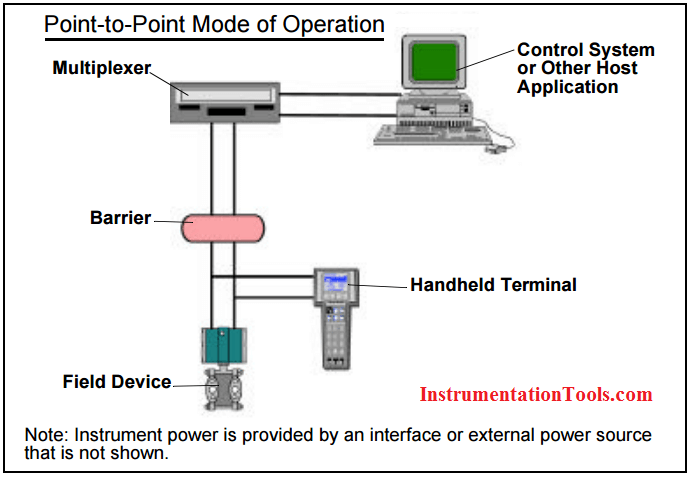
HART networks can operate in two configurations: point-to-point and multidrop mode. In the point-to-point network, the traditional 4–20 mA current signal is used to control the process and remains unaffected by HART signal. The configuration parameters, etc., are transferred digitally over the HART protocol. The point-to-point scheme is shown in Below Figure. The digital HART signal is used for commissioning, maintenance, and diagnostic purposes.
HART multidrop communication networks are used when the devices are widely spaced. As shown in Below Figure, only two wires are required to communicate with the master. If required, intrinsic safety barriers and auxiliary power supply for up to 15 devices can be incorporated in this mode. All polling addresses of the devices are set at greater than zero and device current limited to a typical value of 4 mA.
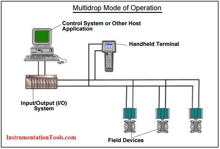
Multidrop networks allow two wire devices to be connected in parallel. Information reading time from a single variable is typically 500 ms and with 15 devices connected to the network; approximately 7.5 s would be required to completely go through the network cycle once.
HART FIELD DEVICE CALIBRATION
HART devices need occasional calibration to ensure that the transducer output, via the different processing blocks, is representing the true process value. Any HART field device has a transducer block, a range block, and a data acquisition (DAQ) block for such calibration.
Calibration of such field devices include the calibration of the digital process value, its proper scaling, converting into some desired range, and finally sending the 4–20 mA current value. The process output successively goes to the transducer block, range or range conversion block, and finally to the DAQ block.
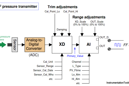
The below Figure shows the calibration steps for a HART-enabled field device. The transducer block involves comparing a simulated transducer value with an internally generated traceable reference. This comparison determines whether calibration of the field device is required, which can be done by using the HART protocol. Calibration is usually performed by providing the field device with exact transducer values—one near the lower limit and the other near the upper limit. Using the HART protocol, the field device then performs the necessary adjustments, if needed.
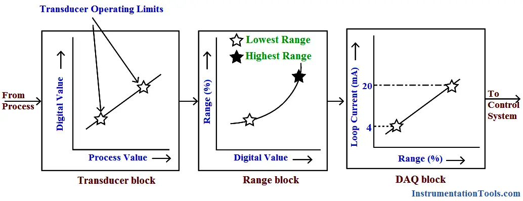
Fig : Calibration of HART field devices
The range block uses the lower and upper range values of 4 and 20 mA, respectively, to convert these transducer values into lower and upper range percent values—the former refers to 0% and the latter 100%. The range block output may be in linear or square root form—as in the case of flowtype PV.
The output of the range block is passed on to the DAQ block, which then converts the percent range values into loop current signals. Calibration of the current loop is not seriously needed because no moving parts are involved. Calibration at 4 mA corresponds to current zero trim and 20 mA is called the current span trim.