Inst ToolsInst ToolsInst Tools
  • Ask
  • Courses
  • Videos
  • Q & A
    • Interview
      • Instrumentation
      • Electronics
      • Electrical
      • Practical Questions
    • MCQ
      • Instrumentation MCQ
      • Electrical MCQ
      • Electronics MCQ
      • Control Systems MCQ
      • Analog Electronics MCQ
      • Digital Electronics MCQ
      • Power Electronics MCQ
      • Microprocessor MCQ
      • Multiple Choice Questions
  • EE
    • Electronics
      • Electronics Q & A
      • Electronic Basics
      • Electronic Devices & Circuits
      • Electronics Animation
      • Digital Electronics
    • Electrical
      • Electrical Basics
      • Electrical Q & A
      • Power Electronics
      • Electrical Machines
      • Electrical Animation
      • Power Systems
      • Switchgear & Protection
      • Transmission & Distribution
  • Measure
    • Control Valves
    • Calibration
    • Temperature
    • Pressure
    • Flow
    • Level
    • Analyzers
    • Switches
    • Vibration
    • Solenoid Valve
  • Control
    • PLC Tutorials
    • Control Systems
    • Safety Instrumented System (SIS)
    • Communication
    • Fire & Gas System
  • More
    • Design
    • Tools
    • Animation
    • Basics
    • Formulas
    • Standards
    • TextBooks
    • Common
    • Software
    • Excel Tools
    • Erection & Commissioning
    • Process Fundamentals
    • Videos
    • Books
Search
All rights reserved. Reproduction in whole or in part without written permission is prohibited.
Reading: Ladder Diagram Example using Memory Bits and Set Coils
Share
Notification Show More
Font ResizerAa
Inst ToolsInst Tools
Font ResizerAa
  • Courses
  • PLC Tutorials
  • Control Systems
Search
  • Ask
  • Courses
  • Videos
  • Q & A
    • Interview
    • MCQ
  • EE
    • Electronics
    • Electrical
  • Measure
    • Control Valves
    • Calibration
    • Temperature
    • Pressure
    • Flow
    • Level
    • Analyzers
    • Switches
    • Vibration
    • Solenoid Valve
  • Control
    • PLC Tutorials
    • Control Systems
    • Safety Instrumented System (SIS)
    • Communication
    • Fire & Gas System
  • More
    • Design
    • Tools
    • Animation
    • Basics
    • Formulas
    • Standards
    • TextBooks
    • Common
    • Software
    • Excel Tools
    • Erection & Commissioning
    • Process Fundamentals
    • Videos
    • Books
Follow US
All rights reserved. Reproduction in whole or in part without written permission is prohibited.
Inst Tools > Blog > PLC Tutorials > Ladder Diagram Example using Memory Bits and Set Coils

Ladder Diagram Example using Memory Bits and Set Coils

In this article, you will learn the PLC ladder diagram example using memory bits and set coils to control the motors.

Last updated: March 21, 2024 4:12 pm
Editorial Staff
PLC Tutorials
No Comments
Share
4 Min Read
SHARE

In this article, you will learn the PLC ladder diagram example using memory bits and set coils to control the motors.

Contents
Memory Bits and Set CoilsPLC Training VideoInputs in PLCOutputs in PLCLadder Diagram for MotorsProgram ExplainedPLC Result

Note: The ladder diagram example is for students and fresh engineering graduates.

Memory Bits and Set Coils

Problem Statement

Design a PLC ladder logic for the following application.

We are using one toggle switch to control four motors.

If Switch 1 is ON, then Motor I, Motor II, Motor III, and Motor IV will be ON.

If Switch 1 is OFF, then Motor I and Motor II, Motor III, and Motor IV remain ON.

PLC Training Video

Watch this video to understand the given example program with a step-by-step approach.

Inputs in PLC

The inputs of this PLC program are given below.

Switch 1: I0.0

Memory bit: M1

Outputs in PLC

The outputs of this PLC program are given below.

Motor 1: Q0.0

Motor 2: Q0.1

Motor 3: Q0.2

Motor 4: Q0.3

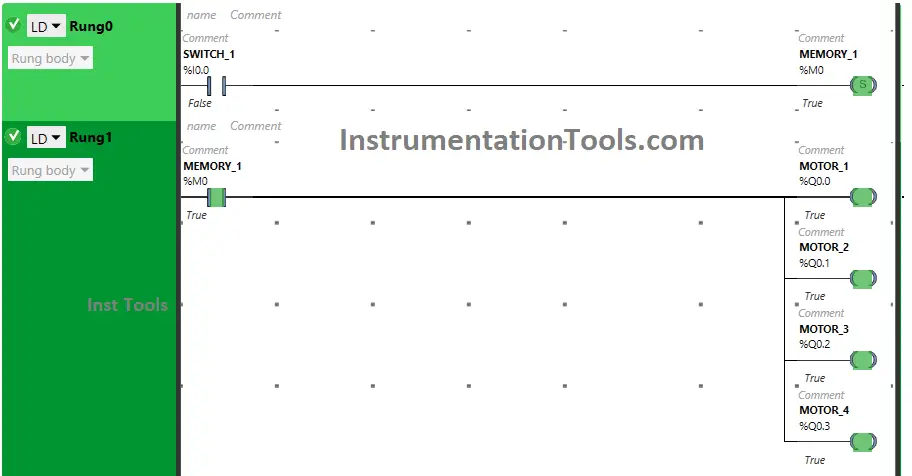
Ladder Diagram for Motors
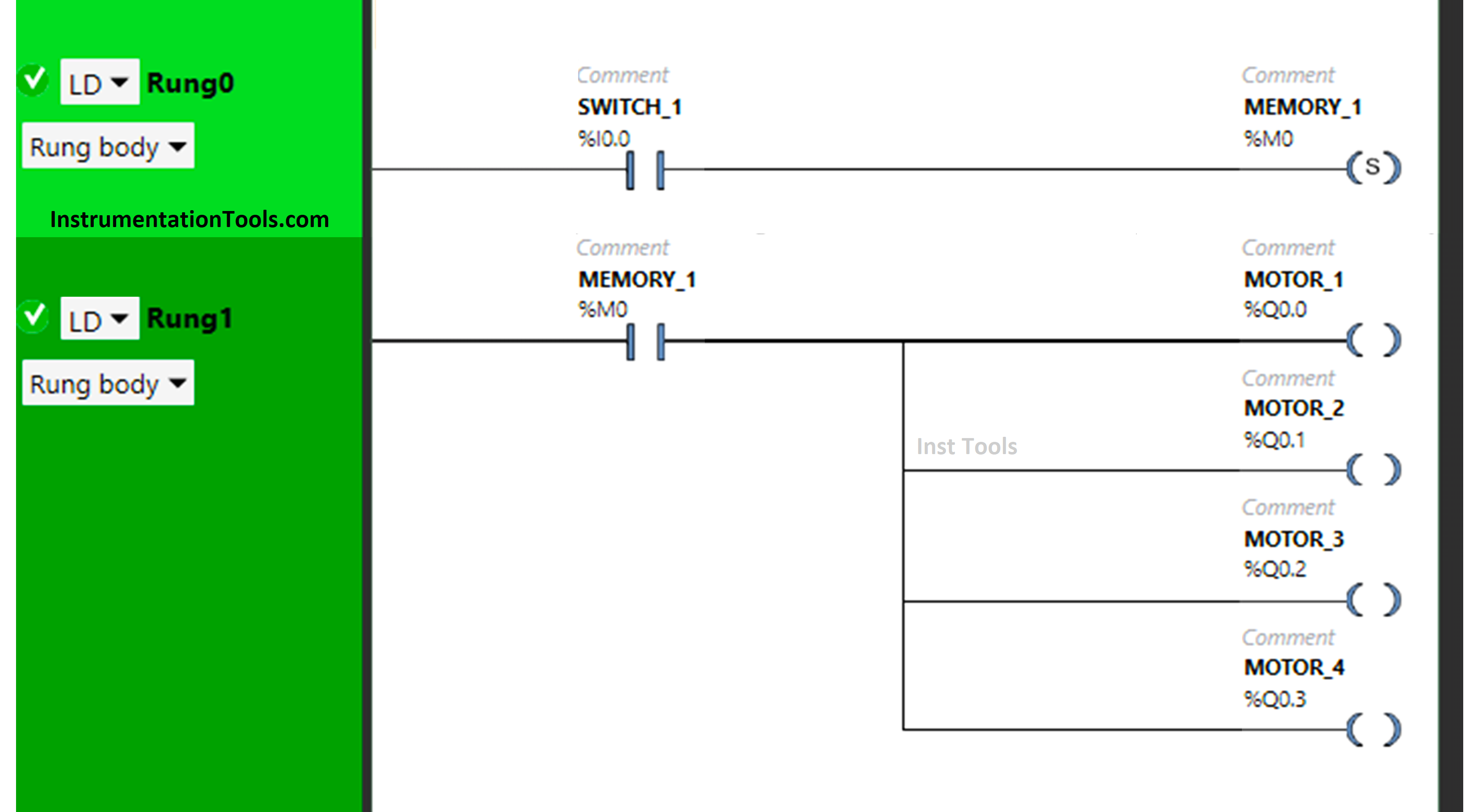
Ladder Diagram Example using Memory Bits and Set Coils

Program Explained

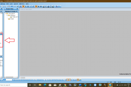
In this program, we used the Schneider Electric PLC software.

In the above program, we have used Normally Open Contact for Switch 1 (I0.0).

We have also used a set coil for the Memory bit (M0).

In Rung1, switch 1 is connected with a set coil for the Memory Bit.

Motor 1, Motor 2, Motor 3, and Motor 4 are connected to the input Memory Bit present in Rung1.

For Motor 1, Motor 2, Motor 3, and MOTOR 4 to turn ON, input Switch 1 should be ON.

All Motors will remain ON if switch 1 is turned OFF as switch 1 is connected with a set coil representing the memory bit.

PLC Result

When Switch 1 is ON
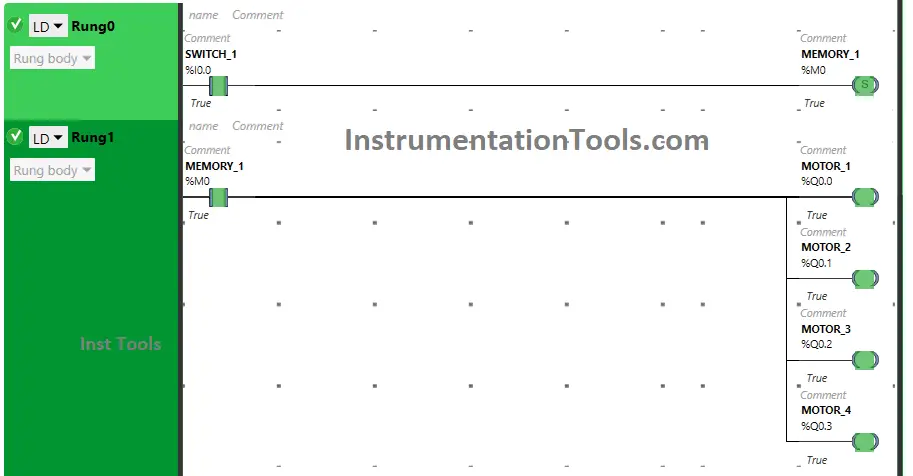
PLC Memory Bits and Set Coils

In Rung 0, there is use of Set Coil for Memory Bit and switch 1 is used as Normally Open Contact. When switch 1 is turned ON, it will allow signal to flow through it and it will make the memory bit true

Then in Rung 1, Motor 1, Motor 2, Motor 3 and Motor 4 connected to the Memory Bit will turn ON.

When Switch 1 is OFF
In a PLC ladder diagram, how do you set an output coil

In Rung 0, Memory Bit remains true even when the input switch 1 is turned OFF.

It is so because the set coil used sets itself true when the input gets ON and retains its true state even when its input is turned OFF. Then in Rung 1, Memory Bit which is still true will keep Motor 1, Motor 2, Motor 3, and Motor 4 ON.

If you liked this article, please subscribe to our YouTube Channel for PLC and SCADA video tutorials.

You can also follow us on Facebook and Twitter to receive daily updates.

Read Next:

  • PLC Program for Stage Control Task
  • How to Get a PLC Programmer Job?
  • Advanced PLC Conveyor Control Program
  • PLC Based Product Sorting Machine
  • Sorting Example PLC Programming
Don't Miss Our Updates
Be the first to get exclusive content straight to your email.
We promise not to spam you. You can unsubscribe at any time.
Invalid email address
You've successfully subscribed !
Redundant Automation Systems – Need and Advantages
How to import GSD files into the TIA Portal? – Siemens PLC
Tank Level Control in PLC
Scale and Normalize Instructions in PLC
PLC Programming for Sequential Batch Mixing System
Share This Article
Facebook Whatsapp Whatsapp LinkedIn Copy Link
Share
Leave a Comment

Leave a Reply Cancel reply

Your email address will not be published. Required fields are marked *

Stay Connected

128.3kFollowersLike
69.1kFollowersFollow
208kSubscribersSubscribe
38kFollowersFollow

Categories

Recent Comments

  • Kamli on Top Free PLC Software
  • Guifty Shimica on Top Non-PLC Certification Courses for Automation Professionals
  • Guifty Shimica on Top Non-PLC Certification Courses for Automation Professionals
  • MIHARITSOA Aina Sitraka on Top Non-PLC Certification Courses for Automation Professionals

Related Articles

Unspecified CPU in Tia Portal

How to Add Unspecified CPU in Tia Portal?

Ladder Logic for Motor Control

PLC Programming for 3 Motors control in Ladder logic

PLC Technique for IO Mapping

PLC Techniques for I/O Mapping

Thin Client in SCADA

What is Thin Client in SCADA? – Purpose, Advantages

Wiring in PLC System

Wiring in a PLC Control Panel

PLC Stop - Start Circuit

Introduction to PLC Ladder Diagrams

Difference between Compact PLC and Modular PLC

Difference between Compact PLC and Modular PLC

Types of PLC Memory

Types of PLC Memory

More Articles

LIFO Instruction in Allen Bradley PLC Programming

LIFO Instruction in PLC

What is an Electrical Drive

What is an Electrical Drive? Types, Advantages, Disadvantages

11 KV Bus A to Bus B Phase Check Problem

11 KV Bus A to Bus B Phase Check Problem

PLC Math instructions

PLC Math instructions

Dual Solenoid Valve on Control Valve

Why we Require Dual SOV on a Control Valve?

RTD with Thermowell

Temperature Sensor Accessories

Top 100 Zigbee Projects for Engineering Students

Top 100 Zigbee Projects for Engineering Students

Difference Between Industrial Computer and Normal Computer

Difference Between Industrial Computer (IPC) and Normal Computer (PC)

Follow US
All rights reserved. Reproduction in whole or in part without written permission is prohibited.
Welcome Back!

Sign in to your account

Username or Email Address
Password

Lost your password?