In this article, you will learn how to read the nameplate details of an industrial electrical motor and understand the basic details.
Most manufacturers display information differently and nameplates often get dirty, damaged, and occasionally removed.
In a plant, the maintenance department needs motor nameplate information throughout the life of the motor. This is to handle tasks like replacing the motor, buying spares, repairing a motor, sizing a VFD, correcting power factor, or doing anything else with a motor.
Motor Nameplate
There are several international standards in naming a motor plate. NEMA and IEC are two. Where NEMA is used in North America, IEC is used in the rest of the world.
For example power of a motor is in HP as per NEMA standard, whereas in IEC standard it is KW.
Voltage
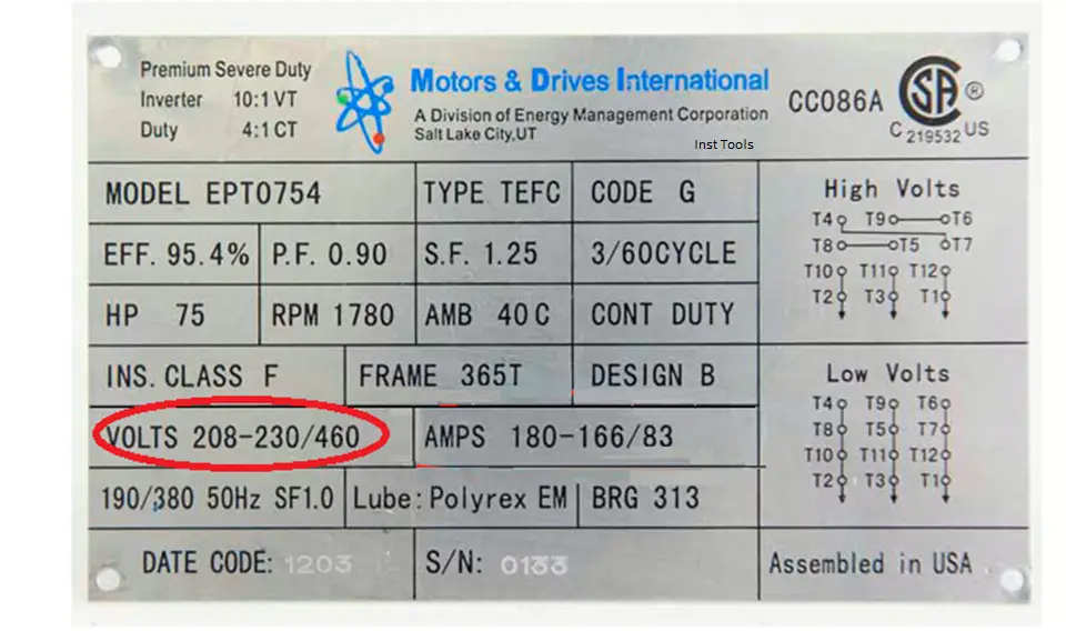
Motors are designed to operate at the voltage indicated on their nameplate. Many industrial motors are designed to run on more than one voltage (line power).
For example, many motors are dual rated and designed to run at 230V and 460V.
Motors typically have a running tolerance of 10% ± of nameplate rated voltage, this means a motor designed to run on 230V can run on 208V (or 240V).
Full Load Amp Rating
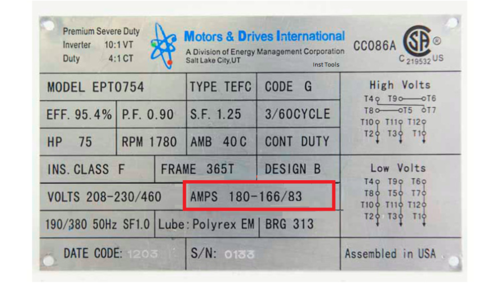
The FLA rating is the rate at which a motor will draw power at 100% rated load and at rated and balanced voltage. This number is extremely important, especially when it comes to electrical components.
Wiring, starter, circuit breaker, and thermal overloads are sized based on full load amp rating.
Phase
Unless you have a unique application, your motor will be rated for single or three-phase input power.
RPM (speed)
The RPM (Revolutions per Minute) listed on the nameplate is the motor shaft speed. The speed of the motor is directly related to the frequency of the line voltage and the number of poles on the motor.
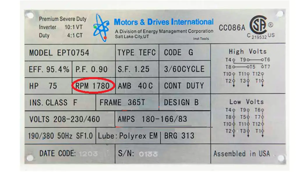
However, depending on the amount of rotor slip the motor was designed for, the RPM may be listed as 1775 or 1750, etc. This number represents what the manufacturer has designed for the motor to rotate at full load at the stated frequency indicated on the nameplate.
Letter design
The design chart provides information on the starting torque of a motor. Design letters B (normal starting torque), C (high starting torque), and D (very high starting torque) are the most common.
The starting torque of a motor is different from the torque during normal operations.
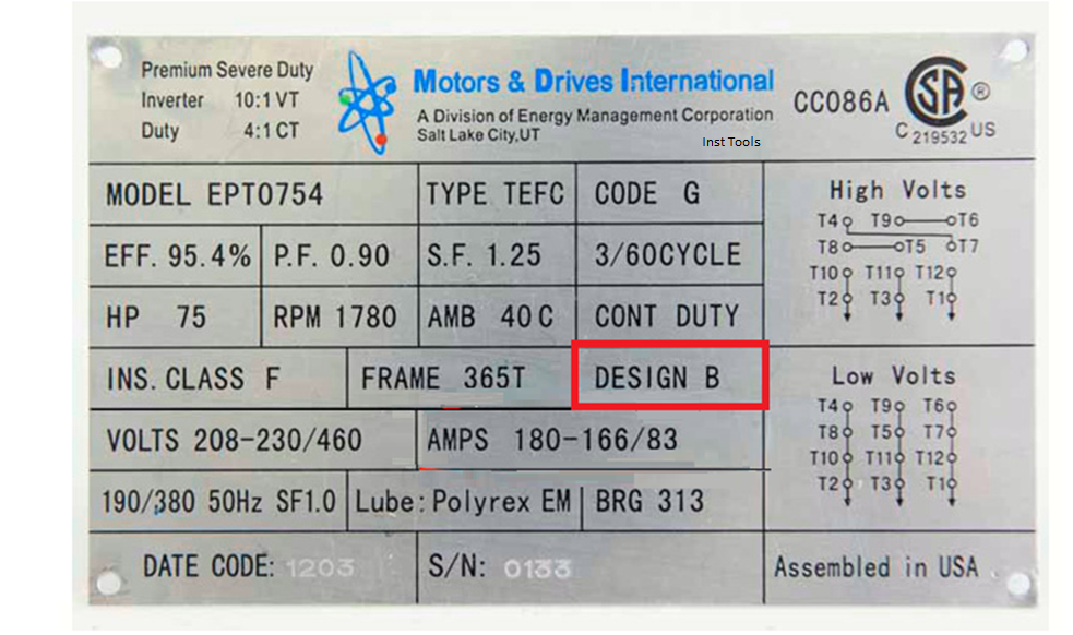
For example, two motors with similar running torque values may have very different starting torque values. A motor used for a centrifugal fan is likely to have a different starting torque requirement than a conveyor.
Frequency
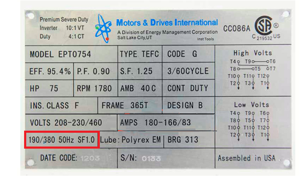
Frequency is the peak-to-peak duration of an AC sine wave (60 HZ = 60 cycles per second). The frequency is directly associated with the speed of the motor.
In North America, the standard frequency is usually 60 HZ. Outside of North America, 50 HZ is usually the standard.
Some nameplates will have multiple frequency ratings.
Code
AC motors running at full voltage will draw a higher current (amps) than during normal operation. This is commonly known as inrush current or inrush current.
These codes represent a range of input currents.
Efficiency
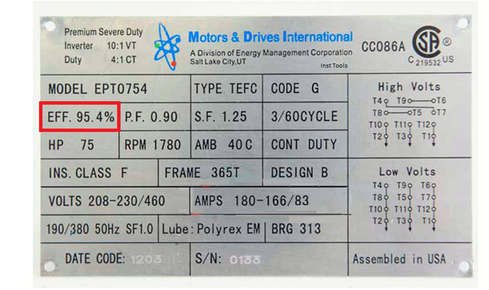
The efficiency rating of a motor measures how well the motor converts electrical energy (input) into mechanical energy (output). It is usually displayed as a decimal.
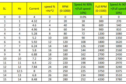
In many applications, a VFD can provide significant savings in operating costs. In some circumstances, using a VFD to reduce speed by 20% can result in 50% energy savings.
However, energy savings will vary based on several factors including motor conditions, application, and energy costs in your area.
Insulation class
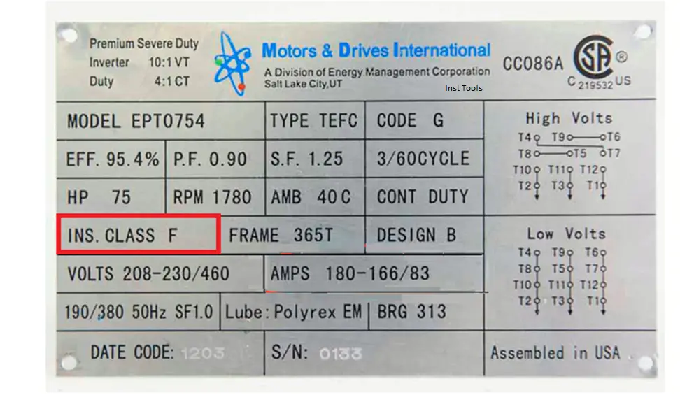
The insulation class describes the ability of a motor to withstand temperatures over time.
B, F, and H are the most commonly used types of motor insulation. Letters later in the alphabet represent insulation that is more capable of withstanding temperature.
So class F can withstand the temperature better than class B.
CT / VT
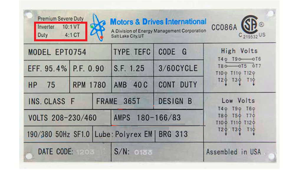
CT means “Constant Torque” and VT means “Variable Torque”.
If these ratings are on your motor nameplate, it usually means the motor is rated for inverter use.
Duty
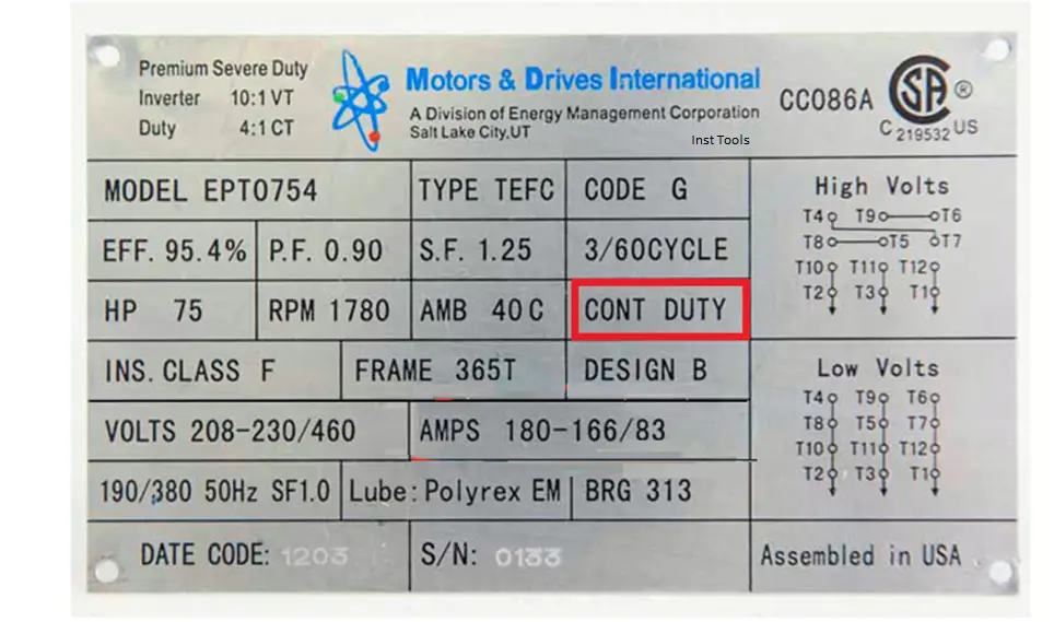
Duty is the time an engine can run without a cool-down period.
Most industrial motors are rated for the continuous duty category.
Type of box
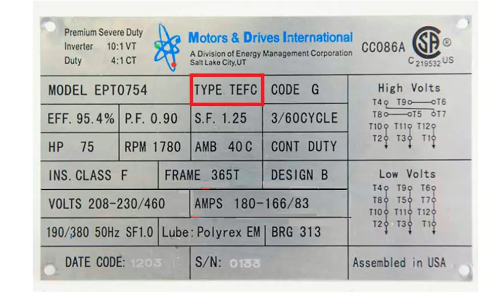
The case type displays information about how well the engine is protected from the environment. There are two types of motor enclosure types, the most common are Open Drip-Proof (ODP) and Totally Enclosed Fan Cooled (TEFC).
ODP (Open or Leak Proof) – is an open enclosure that allows air to flow freely within the windings. It is protected from liquid droplets falling from an angle of 0 to 15 degrees, but it is not waterproof.
TEFC (Totally Enclosed Fan Cooled) – Prevents air from flowing freely into the motor. The motor is cooled by a fan that blows air outside the cabinet. A TEFC is not completely airtight or watertight. External contaminants can get into the engine, but this usually does not interfere with normal operations.
Bearings
The motor nameplate may include bearing information.
There can be two specifications of bearings.
The drive-shaft bearing and the opposite drive-shaft bearing.
The difference between these two is the location of the engine. The driveshaft bearing is located near where the driveshaft extends out of the engine. The opposite drive shaft bearing is on the opposite side of the driveshaft.
Each manufacturer has its own way of displaying the to bearing information and this can vary widely between manufacturers.
Motor Voltage connection diagrams
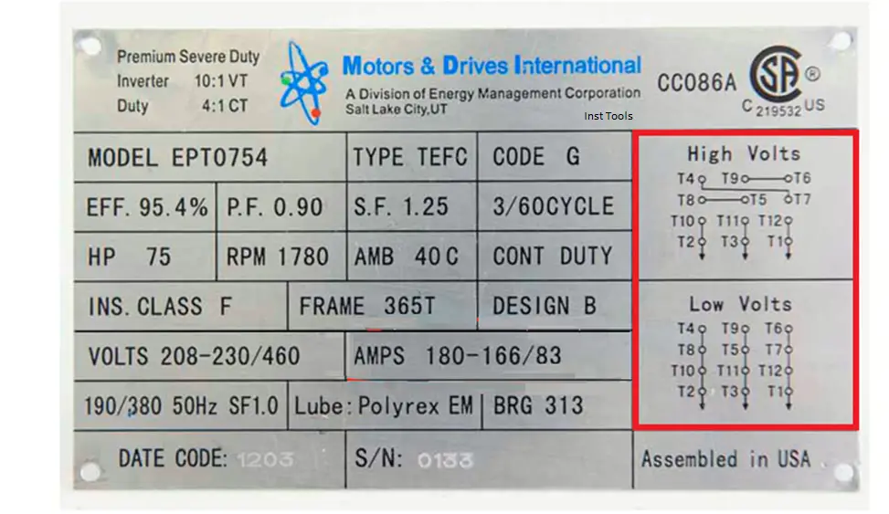
The connection diagrams show information on how to connect the motor to the proper voltage.
Some motors are designed and manufactured to handle multiple voltages so there may be more than one diagram. It is important to carefully select the correct diagram.
Improper wiring connection will damage the motor.
Motor model number and serial number
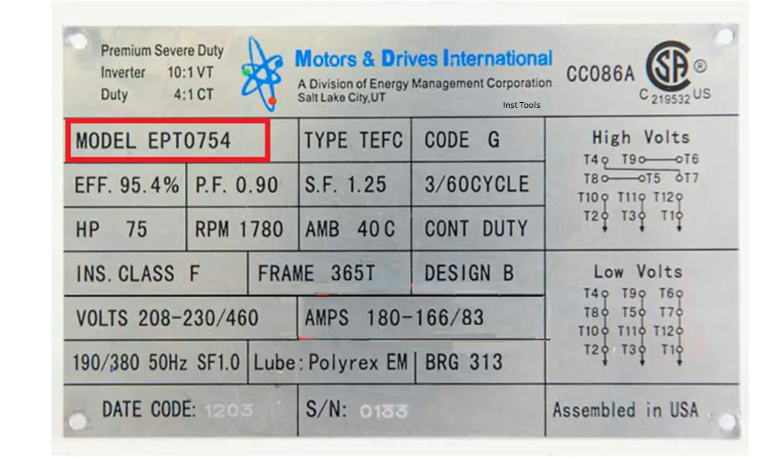
These are two numbers with which the manufacturer identifies the equipment.