Inst ToolsInst ToolsInst Tools
  • Ask
  • Courses
  • Videos
  • Q & A
    • Interview
      • Instrumentation
      • Electronics
      • Electrical
      • Practical Questions
    • MCQ
      • Instrumentation MCQ
      • Electrical MCQ
      • Electronics MCQ
      • Control Systems MCQ
      • Analog Electronics MCQ
      • Digital Electronics MCQ
      • Power Electronics MCQ
      • Microprocessor MCQ
      • Multiple Choice Questions
  • EE
    • Electronics
      • Electronics Q & A
      • Electronic Basics
      • Electronic Devices & Circuits
      • Electronics Animation
      • Digital Electronics
    • Electrical
      • Electrical Basics
      • Electrical Q & A
      • Power Electronics
      • Electrical Machines
      • Electrical Animation
      • Power Systems
      • Switchgear & Protection
      • Transmission & Distribution
  • Measure
    • Control Valves
    • Calibration
    • Temperature
    • Pressure
    • Flow
    • Level
    • Analyzers
    • Switches
    • Vibration
    • Solenoid Valve
  • Control
    • PLC Tutorials
    • Control Systems
    • Safety Instrumented System (SIS)
    • Communication
    • Fire & Gas System
  • More
    • Design
    • Tools
    • Animation
    • Basics
    • Formulas
    • Standards
    • TextBooks
    • Common
    • Software
    • Excel Tools
    • Erection & Commissioning
    • Process Fundamentals
    • Videos
    • Books
Search
All rights reserved. Reproduction in whole or in part without written permission is prohibited.
Reading: PLC Sequential Operation Example Program
Share
Notification Show More
Font ResizerAa
Inst ToolsInst Tools
Font ResizerAa
  • Courses
  • PLC Tutorials
  • Control Systems
Search
  • Ask
  • Courses
  • Videos
  • Q & A
    • Interview
    • MCQ
  • EE
    • Electronics
    • Electrical
  • Measure
    • Control Valves
    • Calibration
    • Temperature
    • Pressure
    • Flow
    • Level
    • Analyzers
    • Switches
    • Vibration
    • Solenoid Valve
  • Control
    • PLC Tutorials
    • Control Systems
    • Safety Instrumented System (SIS)
    • Communication
    • Fire & Gas System
  • More
    • Design
    • Tools
    • Animation
    • Basics
    • Formulas
    • Standards
    • TextBooks
    • Common
    • Software
    • Excel Tools
    • Erection & Commissioning
    • Process Fundamentals
    • Videos
    • Books
Follow US
All rights reserved. Reproduction in whole or in part without written permission is prohibited.
Inst Tools > Blog > PLC Tutorials > PLC Sequential Operation Example Program

PLC Sequential Operation Example Program

Design a PLC program and explain the sequential operation using a push button example ladder logic programming.

Last updated: March 4, 2021 10:51 am
Editorial Staff
PLC Tutorials
No Comments
Share
2 Min Read
SHARE

Write a PLC program so that when the step push button is pressed and qw0 is equal to zero the first bit in the output word is energized by one, and when the step push button is pressed again the next bit is energized and so on till the reset push button is pressed.

Contents
Inputs & OutputsPLC Sequential Operation ExamplePLC ProgramRead Next:

This is an example of sequential operation of output bits using one push buttons.

Note: the best practice to learn the PLC programming is to start writing the PLC program, take your time before you review the answer. 

Inputs & Outputs

I0.0: step Push Button (Normally open contact)

I0.1: reset Push Button (Normally open contact)

Qw0: output word i.e from (Q0.0 to Q1.7) 

PLC Sequential Operation Example
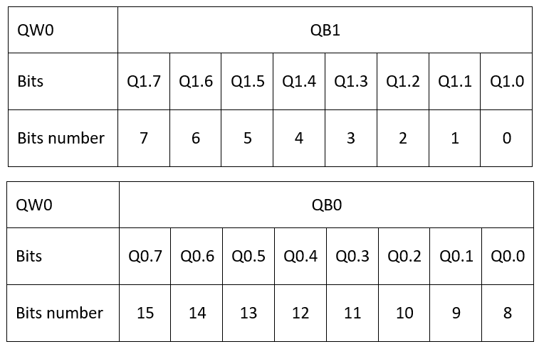
Memory Word order of bits

Before you start your programming you have to understand the order of bits when you hear memory word, here in the table attached you can figure out the address of any bit number.

PLC Program
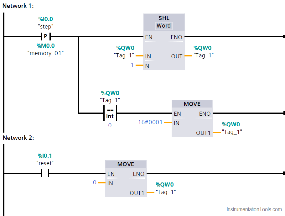
PLC Sequential Operation Example Program

Network 1:

In every time the positive edge of step push button is detected the shift left instruction moves 1 to next bit of the QW0,

if QW0 = 0 the move instruction is energized and move the hexadecimal value 16#8000 to QW0 which is equivalent to 1000 0000 0000 0000.

Network 2:

In any time when the reset push button is pressed, 0 is moved to QW0 which will reset all the output word.

Author: Karim Ali Anwar

If you liked this article, then please subscribe to our YouTube Channel for PLC and SCADA video tutorials.

You can also follow us on Facebook and Twitter to receive daily updates.

Read Next:

  • PLC Permissive Inputs
  • PLC Sequential Operation
  • PLC Counter Comparison
  • Packaging Carton PLC Logic
  • Delta PLC Simulator
Don't Miss Our Updates
Be the first to get exclusive content straight to your email.
We promise not to spam you. You can unsubscribe at any time.
Invalid email address
You've successfully subscribed !
Automatic Door Operation PLC Programming and Simulation
Safety Door Interlock PLC Program
How CPU Execute Program in Siemens PLC?
Increment & Decrement Instructions in CX-Programmer (OMRON)
Various Control Methods in Servo Motor Drives
Share This Article
Facebook Whatsapp Whatsapp LinkedIn Copy Link
Share
Leave a Comment

Leave a Reply Cancel reply

Your email address will not be published. Required fields are marked *

Stay Connected

128.3kFollowersLike
69.1kFollowersFollow
208kSubscribersSubscribe
38kFollowersFollow

Categories

Recent Comments

  • Kamli on Top Free PLC Software
  • Guifty Shimica on Top Non-PLC Certification Courses for Automation Professionals
  • Guifty Shimica on Top Non-PLC Certification Courses for Automation Professionals
  • MIHARITSOA Aina Sitraka on Top Non-PLC Certification Courses for Automation Professionals

Related Articles

PLC Problems Troubleshooting

PLC Problems Troubleshooting

Configuration of Siemens Scada and PLC

#12 PLC Best Practices – Validate Inputs based on Physical Plausibility

PLC Program for Temperature Control using Thermostat

PLC Program for Temperature Control using Thermostat

Difference Between PNP and NPN Sensors

Difference Between PNP and NPN Sensors

Modbus in Industrial Networks

How Modbus is used in Industrial Networks?

Manual sequential logic in Schneider PLC

Programming Schneider PLC Manual Sequential Machine

PLC Training Course

#17 PLC Best Practices – Log PLC Uptime and Trend it on HMI

Types of Scan Time in a PLC

Programmable Logic Controller (PLC) Scan Time – Types, Theory

More Articles

Difference Between SCADA and HMI

Difference Between SCADA and HMI

DCS Troubleshooting Control Valve Loop

DCS Troubleshooting Control Valve Loop

ISO 5167 Orifice Plate Types

Readers Questions on Flow Transmitter

DCS Marshalling Cabinet Checks

PLC, DCS, and ESD Marshalling Cabinet Checks

Densitometers Principle

Vibrating Tube Densitometers Working Principle

Abbreviations of Pressure, Temperature & Flow

Abbreviations of Pressure, Temperature & Flow

Calculate DPT Calibrated Range

Calculate the Transmitter Values

Motor STAR - DELTA Working principle

Motor STAR – DELTA Starter Working Principle

Follow US
All rights reserved. Reproduction in whole or in part without written permission is prohibited.
Welcome Back!

Sign in to your account

Username or Email Address
Password

Lost your password?