U-tube Water Manometer
Question 1:
How much pressure is being applied to this U-tube water manometer, in units of “inches of water column” and “pounds per square inch”?
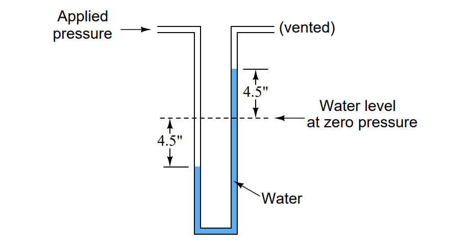
What would happen to the liquid levels if the water were replaced by an oil with a lesser density? Given the same applied pressure, would the distance between the two liquid columns be greater, less, or the same as shown in the above illustration?
Answer:
Applied pressure = 9 ”W.C., which is equal to 0.32514 PSI.
For the same applied pressure, the distance between the two liquid columns will be greater than with water. In other words, for a pressure of 9” W.C., there will be more than 9 inches of vertical distance separating the two liquid columns.
Essentially, manometers work on the principle of balanced pressures: the applied gas pressure forces the liquid columns to shift height. When they do so, they generate a hydrostatic pressure proportional to their differential height. When this hydrostatic pressure equals the applied pressure, the liquid columns stop moving and a condition of equilibrium is reached.
If a lighter fluid such as oil is used instead of water, a greater height will have to be developed to generate the same amount of hydrostatic pressure to oppose the applied gas pressure and reach equilibrium. Conversely, if a heavier (denser) liquid such as mercury were to be used, a much smaller vertical height would develop between the two columns for the same pressure.
Question 2:
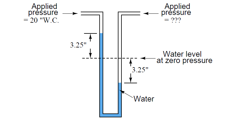
How much pressure, in units of “inches of water column,” is being applied to the right-hand tube of this U-tube water manometer?
Also, convert this pressure into units of Pascals.
Answer:
Pressure applied to right-hand tube = 26.5 ”W.C = 6600.8 Pa.
Question 3:
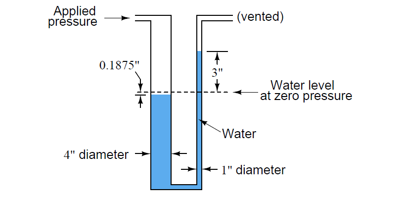
How much pressure is being applied to this U-tube water manometer, in units of “inches of water column” and “pounds per square inch”?
Answer:
Applied pressure = 3.1875 ”W.C., which is equal to 0.1152 PSI.
Read Next:
- what is a Bubbler System?
- Elastic Diaphragm Gauge
- Hydrostatic Level Transmitter
- Transformer Operation
- What is Water Cut Meter?
Credits: Tony Kuphaldt