Inst ToolsInst ToolsInst Tools
  • Ask
  • Courses
  • Videos
  • Q & A
    • Interview
      • Instrumentation
      • Electronics
      • Electrical
      • Practical Questions
    • MCQ
      • Instrumentation MCQ
      • Electrical MCQ
      • Electronics MCQ
      • Control Systems MCQ
      • Analog Electronics MCQ
      • Digital Electronics MCQ
      • Power Electronics MCQ
      • Microprocessor MCQ
      • Multiple Choice Questions
  • EE
    • Electronics
      • Electronics Q & A
      • Electronic Basics
      • Electronic Devices & Circuits
      • Electronics Animation
      • Digital Electronics
    • Electrical
      • Electrical Basics
      • Electrical Q & A
      • Power Electronics
      • Electrical Machines
      • Electrical Animation
      • Power Systems
      • Switchgear & Protection
      • Transmission & Distribution
  • Measure
    • Control Valves
    • Calibration
    • Temperature
    • Pressure
    • Flow
    • Level
    • Analyzers
    • Switches
    • Vibration
    • Solenoid Valve
  • Control
    • PLC Tutorials
    • Control Systems
    • Safety Instrumented System (SIS)
    • Communication
    • Fire & Gas System
  • More
    • Design
    • Tools
    • Animation
    • Basics
    • Formulas
    • Standards
    • TextBooks
    • Common
    • Software
    • Excel Tools
    • Erection & Commissioning
    • Process Fundamentals
    • Videos
    • Books
Search
All rights reserved. Reproduction in whole or in part without written permission is prohibited.
Reading: Questions on Piping and Instrumentation Diagrams
Share
Notification Show More
Font ResizerAa
Inst ToolsInst Tools
Font ResizerAa
  • Courses
  • PLC Tutorials
  • Control Systems
Search
  • Ask
  • Courses
  • Videos
  • Q & A
    • Interview
    • MCQ
  • EE
    • Electronics
    • Electrical
  • Measure
    • Control Valves
    • Calibration
    • Temperature
    • Pressure
    • Flow
    • Level
    • Analyzers
    • Switches
    • Vibration
    • Solenoid Valve
  • Control
    • PLC Tutorials
    • Control Systems
    • Safety Instrumented System (SIS)
    • Communication
    • Fire & Gas System
  • More
    • Design
    • Tools
    • Animation
    • Basics
    • Formulas
    • Standards
    • TextBooks
    • Common
    • Software
    • Excel Tools
    • Erection & Commissioning
    • Process Fundamentals
    • Videos
    • Books
Follow US
All rights reserved. Reproduction in whole or in part without written permission is prohibited.
Inst Tools > Blog > Instrumentation Interview Questions > Questions on Piping and Instrumentation Diagrams

Questions on Piping and Instrumentation Diagrams

Last updated: June 20, 2020 10:58 am
Editorial Staff
Instrumentation Interview Questions
1 Comment
Share
6 Min Read
SHARE

In this post, we shared the 12 Questions on Piping and Instrumentation Diagrams related to the steam heat exchanger level & analytical control loop.

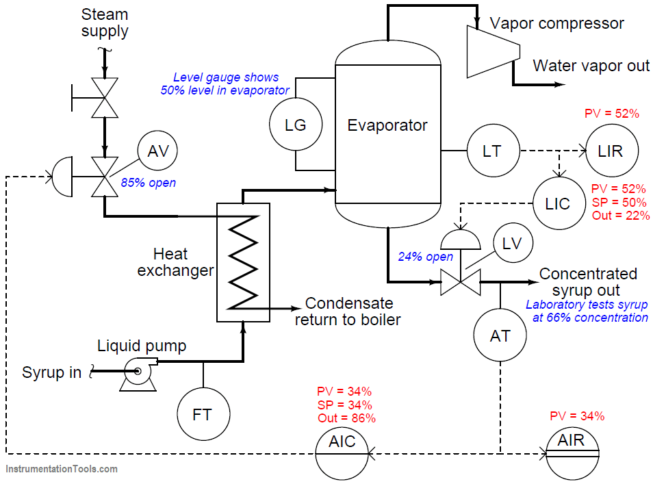
In this process, maple syrup is heated as it passes through a steam heat exchanger, then enters an evaporator where the water boils off. The purpose of this is to raise the sugar concentration of the syrup, making it suitable for use as a food topping.

A level control system (LT, LIC, and LV) maintains constant syrup level inside the evaporator, while an analytical control system (AT, AIR, AC, and AV) monitors the sugar concentration of the syrup and adjusts steam flow to the heat exchanger accordingly.

Questions on Piping and Instrumentation Diagrams

Question 1:

Suppose the steam tubes inside the heat exchanger become coated with residue from the raw maple syrup, making it more difficult for heat to transfer from the steam to the syrup. This makes the heat exchanger less efficient, which will undoubtedly affect the process.

Describe in detail the effect this heat exchanger problem will have on the performance of the analytical control system (or loop).

Answer:

The analytical control system (or lo0p) should still be able to maintain sugar concentration at setpoint, unless the heat exchanger fouling is so extreme that even a wide-open steam valve does not heat the incoming syrup enough to sufficiently concentrate it.

Question 2:

Suppose the heat exchanger fouling really is this bad, but we cannot fix the heat exchanger with the tools we have available. What would you recommend the operator do to make this system produce on-spec syrup?

Question 3:

Suppose a process operator accidentally leaves the manual block valve locked and tagged shut following an overhaul of the process, so that no steam can enter the heat exchanger.

Describe how both control systems will respond over time to this process condition.

Question 4:

Explain the function of a heat exchanger, describing its construction as well.

Question 5:

Why do you think it is important to monitor and control the level of syrup inside the evaporator?

Question 6:

How realistic do you think it is that a person might accidentally leave their lock and tag on a closed valve following a long period of downtime?

Question 7:

Suppose the operations personnel of this maple syrup processing facility wished to have an automatic method for detecting heat exchanger fouling. What variable(s) could be measured in this process to indicate a fouled heat exchanger?

Question 8:

What economic effect will this fouling have on the process? In other words, does the process become more or less profitable as a result of the heat exchanger fouling?

Question 9:

Suppose an operator notices the sugar concentration holding precisely to the setpoint, and decides the controller need not be in automatic mode anymore. After switching the AC to “manual” mode, the operator then leaves the controller to attend to other duties.

Describe in detail the effect this change in controller mode may (or will) have on the operation of this process.

Question 10:

Describe at least one appropriate use of manual mode (in PID controller), and explain why manual mode is such a valuable feature in a process controller.

Question 11:

Examine the live variable values shown in the above diagram, and then determine where any problems may exist in this syrup concentrating system.

Heat Exchanger Piping and Instrumentation

Answer:

The one glaring discrepancy we see here is between the laboratory’s measurement of syrup concentration and what the AIC and AIR indicate.

Given that both the AIC and AIR agree with each other on PV value, we may conclude that the signal to both of these instruments corresponds to a 34% measurement.

The problem is either the transmitter (AT) mis-measuring the syrup concentration, or else it is sensing the concentration okay but outputting the wrong 4-20 mA signal nonetheless, or else the laboratory made a measurement error of their own and incorrectly reported a syrup concentration that is too high.

We also see some minor discrepancies between controller output indications and actual valve stem positions, but these are small enough to ignore.

Likewise, the discrepancy between the level gauge (LG) indication and the level controller/recorder indications is small enough that it does not pose a serious problem.

Question 12:

A valuable principle to apply in a diagnostic scenario such as this is the correspondence: identifying which variables correspond at different points within the system, and which do not. Apply this comparative test to the variables scenario shown in the above diagram, and use the results to defend your answer of where the problem is located and what type of problem it is.

Share your Answers with us through comments.

Credits: Tony R. Kuphaldt

Read Next:

  • Instrumentation Diagrams
  • Loop Diagrams
  • 5 Valve Manifold
  • PID Controller
  • On/off Control
Don't Miss Our Updates
Be the first to get exclusive content straight to your email.
We promise not to spam you. You can unsubscribe at any time.
Invalid email address
You've successfully subscribed !
Conductivity Analyzers Interview Questions & Answers
Cables and Cable Glands Questions and Answers
Valve Technician Interview Questions
IoT Interview Questions and Answers
Siemens PLC Interview Questions and Answers
Share This Article
Facebook Whatsapp Whatsapp LinkedIn Copy Link
Share
1 Comment
  • Tim Howell PE (Control Systems) says:
    February 1, 2020 at 12:17 am

    Oh cool! Great questions Tony! I really like these…

    Reply

Leave a Reply Cancel reply

Your email address will not be published. Required fields are marked *

Stay Connected

128.3kFollowersLike
69.1kFollowersFollow
208kSubscribersSubscribe
38kFollowersFollow

Categories

Recent Comments

  • Kamli on Top Free PLC Software
  • Guifty Shimica on Top Non-PLC Certification Courses for Automation Professionals
  • Guifty Shimica on Top Non-PLC Certification Courses for Automation Professionals
  • MIHARITSOA Aina Sitraka on Top Non-PLC Certification Courses for Automation Professionals

Related Articles

Top 100 Instrumentation Engineering Questions & Answers

Top 100 Instrumentation Engineering Questions & Answers

Control Valves Multiple Choice Questions

Control Valves Multiple Choice Questions

Sensors & Transducers Questions and Answers

Top 100 Sensors & Transducers Questions and Answers for Freshers

Ethernet Questions and Answers

Ethernet Communication Interview Questions & Answers

PLC Interview Questions and Answers

PLC Interview Questions and Answers

Functional Safety Exam Questions & Answers

Functional Safety Questions & Answers

Interview Questions on Industrial Wireless

Interview Questions on Industrial Wireless

Guided Wave Radar Questions and Answers

Guided Wave Radar Questions and Answers

More Articles

Quiz on Alternators, Motors, and Transformers

200+ Quiz on Alternators, Motors, and Transformers

Difference Between MPCB and MCCB

Difference Between MPCB and MCCB

Difference between Motion Controller and PLC

Difference between Motion Controller and PLC

Measuring Instruments Questions and Answers

150+ Measuring Instruments Questions and Answers

How Nuclear Radiation is used to Measure Coke Dust Level?

How Nuclear Radiation is used to Measure Coke Dust Level?

Determine Calibration Range of Pneumatic Pressure Transmitter

Determine Calibration Range of Pneumatic Pressure Transmitter

Power MOSFET Safe Operating Area

Power MOSFET Safe Operating Area

neutral-grounding-practice-in-power-system

Neutral Grounding Practice in Power System

Follow US
All rights reserved. Reproduction in whole or in part without written permission is prohibited.
Welcome Back!

Sign in to your account

Username or Email Address
Password

Lost your password?