Inst ToolsInst ToolsInst Tools
  • Courses
  • Videos
  • Q & A
    • Interview
      • Instrumentation
      • Electronics
      • Electrical
      • Practical Questions
    • MCQ
      • Instrumentation MCQ
      • Electrical MCQ
      • Electronics MCQ
      • Control Systems MCQ
      • Analog Electronics MCQ
      • Digital Electronics MCQ
      • Power Electronics MCQ
      • Microprocessor MCQ
      • Multiple Choice Questions
  • EE
    • Electronics
      • Electronics Q & A
      • Electronic Basics
      • Electronic Devices & Circuits
      • Electronics Animation
      • Digital Electronics
    • Electrical
      • Electrical Basics
      • Electrical Q & A
      • Power Electronics
      • Electrical Machines
      • Electrical Animation
      • Power Systems
      • Switchgear & Protection
      • Transmission & Distribution
  • Measure
    • Control Valves
    • Calibration
    • Temperature
    • Pressure
    • Flow
    • Level
    • Analyzers
    • Switches
    • Vibration
    • Solenoid Valve
  • Control
    • PLC Tutorials
    • Control Systems
    • Safety Instrumented System (SIS)
    • Communication
    • Fire & Gas System
  • More
    • Design
    • Tools
    • Animation
    • Basics
    • Formulas
    • Standards
    • TextBooks
    • Common
    • Software
    • Excel Tools
    • Erection & Commissioning
    • Process Fundamentals
    • Videos
    • Books
Search
All rights reserved. Reproduction in whole or in part without written permission is prohibited.
Reading: Voltage Polarity and Current Direction
Share
Notification Show More
Font ResizerAa
Inst ToolsInst Tools
Font ResizerAa
  • Courses
  • PLC Tutorials
  • Control Systems
Search
  • Courses
  • Videos
  • Q & A
    • Interview
    • MCQ
  • EE
    • Electronics
    • Electrical
  • Measure
    • Control Valves
    • Calibration
    • Temperature
    • Pressure
    • Flow
    • Level
    • Analyzers
    • Switches
    • Vibration
    • Solenoid Valve
  • Control
    • PLC Tutorials
    • Control Systems
    • Safety Instrumented System (SIS)
    • Communication
    • Fire & Gas System
  • More
    • Design
    • Tools
    • Animation
    • Basics
    • Formulas
    • Standards
    • TextBooks
    • Common
    • Software
    • Excel Tools
    • Erection & Commissioning
    • Process Fundamentals
    • Videos
    • Books
Follow US
All rights reserved. Reproduction in whole or in part without written permission is prohibited.
Inst Tools > Blog > Electrical Theory > Voltage Polarity and Current Direction

Voltage Polarity and Current Direction

Last updated: July 23, 2018 2:55 pm
Editorial Staff
Electrical Theory
1 Comment
Share
2 Min Read
SHARE

Before understanding the laws associated with complex DC circuit analysis, the importance of voltage polarity and current direction must be understood. This article will introduce the polarities and current direction associated with DC circuits.

Contents
Conventional and Electron FlowPolarities

Conventional and Electron Flow

The direction of electron flow is from a point of negative potential to a point of positive potential. The direction of positive charges, or holes, is in the opposite direction of electron flow. This flow of positive charges is known as conventional flow.

All of the electrical effects of electron flow from negative to positive, or from a high potential to a lower potential, are the same as those that would be created by flow of positive charges in the opposite direction; therefore, it is important to realize that both conventions are in use, and they are essentially equivalent. In this manual, the electron flow convention is used.

Polarities

All voltages and currents have polarity as well as magnitude. In a series circuit, there is only one current, and its polarity is from the negative battery terminal through the rest of the circuit to the positive battery terminal. Voltage drops across loads also have polarities.

The easiest way to find these polarities is to use the direction of the electron current as a basis. Then, where the electron current enters the load, the voltage is negative (Figure 31). This holds true regardless of the number or type of loads in the circuit. The drop across the load is opposite to that of the source. The voltage drops oppose the source voltage and reduce it for the other loads. This is because each load uses energy, leaving less energy for other loads.

Voltage Polarities

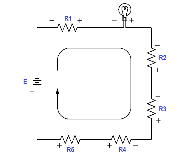
Figure 31 Voltage Polarities

Don't Miss Our Updates
Be the first to get exclusive content straight to your email.
We promise not to spam you. You can unsubscribe at any time.
Invalid email address
You've successfully subscribed !

Recommended Articles

Y and Delta Resistor Network Calculations
Discharge and Charging of Lead-Acid Battery
What is Electricity ?
Types of Capacitors
AC Generation Analysis : Effective Values, Phase Angle and Frequency
Inductance and Inductive Reactance
Share This Article
Facebook Whatsapp Whatsapp LinkedIn Copy Link
Share
1 Comment
  • m.seibel says:
    May 6, 2021 at 1:19 am

    This would be more to the point in answering a simple query.
    ‘The direction of electron flow is from negative potential to positive potential.
    The direction of conventional flow is positive potential to negative potential’.

    Conventional and Electron Flow (present post)
    The direction of electron flow is from a point of negative potential to a point of positive potential. The direction of positive charges, or holes, is in the opposite direction of electron flow. This flow of positive charges is known as conventional flow.

    Reply

Leave a Reply Cancel reply

Your email address will not be published. Required fields are marked *

Stay Connected

128.3kFollowersLike
69.1kFollowersFollow
208kSubscribersSubscribe
38kFollowersFollow

Categories

Recent Comments

  • William Snyder on Top Non-PLC Certification Courses for Automation Professionals
  • Kamli on Top Free PLC Software
  • Guifty Shimica on Top Non-PLC Certification Courses for Automation Professionals
  • Guifty Shimica on Top Non-PLC Certification Courses for Automation Professionals

Related Articles

Generator Action in a Motor

Generator Action in a Motor

Starting a Synchronous Motor

Starting a Synchronous Motor

Transformer Efficiency and Loses Formula

Transformer Losses and Efficiency

Inductive Time Constant

Inductive Time Constant

AC Generator Operation

AC Generator Theory

Inductor Principle

Inductor

circuit breaker principle

What is a circuit breaker ?

Left-Hand Rule for Current-Carrying Conductors

DC Motor Theory

More Articles

100 Digital Electronics and Microprocessor Questions for Practice Exam

100 Digital Electronics and Microprocessor Questions for Practice Exam

Positive Feedback Principle

What is Feedback ?

4-20mA Image

4-20mA Graphical Calculations

Pre-Startup Safety Review (PSSR)

Pre-Startup Safety Review (PSSR)

Zone vs Class - Division

Zone vs Class / Division

Select Security type Intouch

How to Add Security in InTouch SCADA?

Comparison of Electrical Protection Relays

Comparison of Electrical Protection Relays

Components of Electrical Motor

What is Electrical Slip Ring? Principle, Types, Advantages, Applications

Follow US
All rights reserved. Reproduction in whole or in part without written permission is prohibited.
Welcome Back!

Sign in to your account

Username or Email Address
Password

Lost your password?