Inst ToolsInst ToolsInst Tools
  • Courses
  • Automation
    • PLC
    • Control System
    • Safety System
    • Communication
    • Fire & Gas System
  • Instrumentation
    • Design
    • Pressure
    • Temperature
    • Flow
    • Level
    • Vibration
    • Analyzer
    • Control Valve
    • Switch
    • Calibration
    • Erection & Commissioning
  • Interview
    • Instrumentation
    • Electrical
    • Electronics
    • Practical
  • Q&A
    • Instrumentation
    • Control System
    • Electrical
    • Electronics
    • Analog Electronics
    • Digital Electronics
    • Power Electronics
    • Microprocessor
  • Request
Search
  • Books
  • Software
  • Projects
  • Process
  • Tools
  • Basics
  • Formula
  • Power Plant
  • Root Cause Analysis
  • Electrical Basics
  • Animation
  • Standards
  • 4-20 mA Course
  • Siemens PLC Course
Reading: Type E thermocouple Calculations
Share
Font ResizerAa
Inst ToolsInst Tools
Font ResizerAa
  • Courses
  • Design
  • PLC
  • Interview
  • Control System
Search
  • Courses
  • Automation
    • PLC
    • Control System
    • Safety System
    • Communication
    • Fire & Gas System
  • Instrumentation
    • Design
    • Pressure
    • Temperature
    • Flow
    • Level
    • Vibration
    • Analyzer
    • Control Valve
    • Switch
    • Calibration
    • Erection & Commissioning
  • Interview
    • Instrumentation
    • Electrical
    • Electronics
    • Practical
  • Q&A
    • Instrumentation
    • Control System
    • Electrical
    • Electronics
    • Analog Electronics
    • Digital Electronics
    • Power Electronics
    • Microprocessor
  • Request
Follow US
All rights reserved. Reproduction in whole or in part without written permission is prohibited.
Inst Tools > Blog > Practical Questions > Type E thermocouple Calculations

Type E thermocouple Calculations

Last updated: June 6, 2018 9:48 am
Editorial Staff
Practical Questions
No Comments
Share
2 Min Read
SHARE

Type E thermocouple

Calculate the amount of voltage “seen” by the voltmeter given the following measurement and reference junction temperatures:
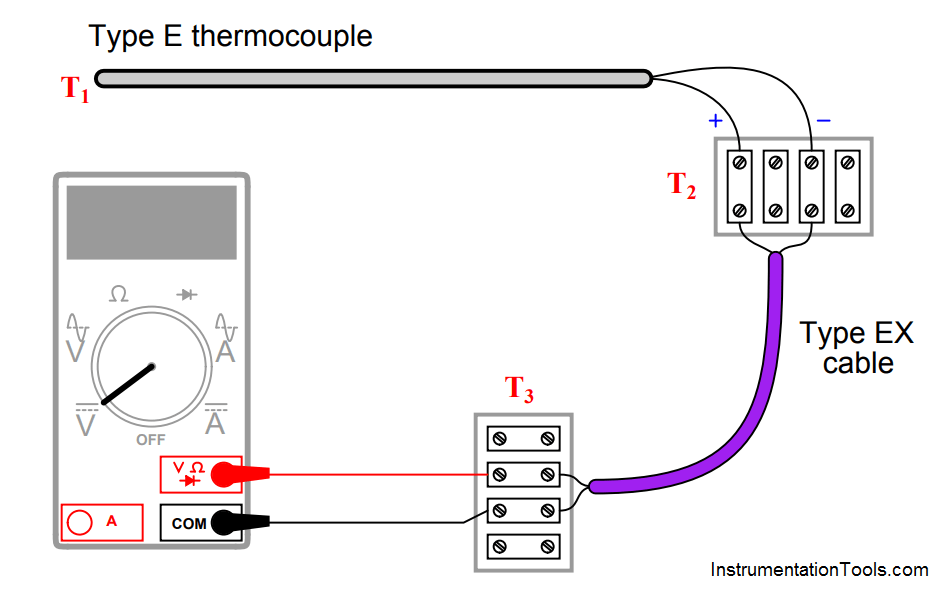
Type E thermocouple

  • T1 = 233 oC ; T2 = 31 oC ; T3 = 25 oC ; Vmeter = __________ mV
  • T1 = 348 oC ; T2 = 40 oC ; T3 = 16 oC ; Vmeter = __________ mV
  • T1 = −161 oC ; T2 = −4 oC ; T3 = 23 oC ; Vmeter = __________ mV
  • T1 = 836 oC ; T2 = 34 oC ; T3 = 19 oC ; Vmeter = __________ mV

Answer :

All answers based on ITS-90 thermocouple table values:

  • T1 = 233 oC ; T2 = 31 oC ; T3 = 25 oC ; Vmeter = 14.395 mV
  • T1 = 348 oC ; T2 = 40 oC ; T3 = 16 oC ; Vmeter = 23.856 mV
  •  T1 = −161 oC ; T2 = −4′oC ; T3 = 23 oC ; Vmeter = −9.039 mV
  • T1 = 836 oC ; T2 = 34 oC ; T3 = 19 oC ; Vmeter = 62.701 mV

Note: all temperatures at T2 are irrelevant because this is a junction between similar metals (type E wires connecting to corresponding type EX extension wires). The reference (cold) junction is where the type EX wires connect to copper, at temperature T3.
Don't Miss Our Updates
Be the first to get exclusive content straight to your email.
We promise not to spam you. You can unsubscribe at any time.
Invalid email address
You've successfully subscribed !

Continue Reading

Calculate Differential Pressure Sensed by Level Transmitter
Determine Level of Liquid in the Vessel and its Specific Gravity
Identify High Flow Alarm and Low Flow Alarm?
Calculate Incident Power in Radar Level Measurement
Find Thermocouple Ouput Voltage
How much Pressure is applied to Inclined Water Manometer?
Share This Article
Facebook Whatsapp Whatsapp LinkedIn Copy Link
Share
Leave a Comment

Leave a Reply Cancel reply

Your email address will not be published. Required fields are marked *

Stay Connected

128.3kFollowersLike
69.1kFollowersFollow
210kSubscribersSubscribe
38kFollowersFollow

Categories

Explore More

10 Questions on Reforming Furnace Control System
Questions on DP Transmitter Wet Leg Compensating Impulse Line
Motor Trip Logic using PLC Programming
Solenoid Valves Questions & Answers – 3
Determine the Problems with Level Transmitter and Gauge
How to Connect Proximity Switch (Sink Type) to Make LED ON ?
How Do You Connect the Differential Pressure Gauge at the Filter?
Upgrading the Electrical System in an Automobile

Keep Learning

displacer level transmitter configuration

Displacer Level Transmitter Questions

measure the temperature of RTD

Measure the Temperature of the RTD

Pneumatic Transmitter

Questions on Pneumatic Transmitter and Repeater

Questions on Level Switches

Questions on Level Switches

Siemens S7-200 PLC

Programmable Logic Controller (PLC) Questions and Answers – 13

Calculate the Magnitude of Hydrostatic Pressure

Calculate the Magnitude of Hydrostatic Pressure

Trends of PV and SP on a process chart

Inspecting the Trends of PV and SP on a Process Chart Recorder

Pneumatic-Level-Transmitter-Value-Struck

Pneumatic Level Transmitter Value Struck?

Learn More

RTD Standards list

RTD Standards

Dynamic Braking Resistor in VFD

Dynamic Braking Resistor in VFD

Measure Frequency using Multimeter

How to measure frequency using Multimeter

Enterprise Resource Planning in Industrial Automation

What is ERP in Industrial Automation? – Enterprise Resource Planning

Digital Electronics Multiple Choice Questions

Transistor Transistor Logic (TTL) Objective Questions

Sample of a production Downtime

How to Use Production Line Failures for Your Gains?

Thermography and Thermometry Objective Questions

Thermography and Thermometry Objective Questions

RTD Calculator Software

RTD Calculator Software

Menu

  • About
  • Privacy Policy
  • Copyright

Quick Links

  • Learn PLC
  • Helping Hand
  • Part Time Job

YouTube Subscribe

Follow US
All rights reserved. Reproduction in whole or in part without written permission is prohibited.
Welcome Back!

Sign in to your account

Username or Email Address
Password

Lost your password?