Inst ToolsInst ToolsInst Tools
  • Courses
  • Automation
    • PLC
    • Control System
    • Safety System
    • Communication
    • Fire & Gas System
  • Instrumentation
    • Design
    • Pressure
    • Temperature
    • Flow
    • Level
    • Vibration
    • Analyzer
    • Control Valve
    • Switch
    • Calibration
    • Erection & Commissioning
  • Interview
    • Instrumentation
    • Electrical
    • Electronics
    • Practical
  • Q&A
    • Instrumentation
    • Control System
    • Electrical
    • Electronics
    • Analog Electronics
    • Digital Electronics
    • Power Electronics
    • Microprocessor
Search
  • Books
  • Software
  • Projects
  • Process
  • Tools
  • Basics
  • Formula
  • Power Plant
  • Root Cause Analysis
  • Electrical Basics
  • Animation
  • Standards
  • 4-20 mA Course
  • Siemens PLC Course
Reading: Types of Load Cells
Share
Notification Show More
Font ResizerAa
Inst ToolsInst Tools
Font ResizerAa
  • Courses
  • Design
  • PLC
  • Interview
  • Control System
Search
  • Courses
  • Automation
    • PLC
    • Control System
    • Safety System
    • Communication
    • Fire & Gas System
  • Instrumentation
    • Design
    • Pressure
    • Temperature
    • Flow
    • Level
    • Vibration
    • Analyzer
    • Control Valve
    • Switch
    • Calibration
    • Erection & Commissioning
  • Interview
    • Instrumentation
    • Electrical
    • Electronics
    • Practical
  • Q&A
    • Instrumentation
    • Control System
    • Electrical
    • Electronics
    • Analog Electronics
    • Digital Electronics
    • Power Electronics
    • Microprocessor
Follow US
All rights reserved. Reproduction in whole or in part without written permission is prohibited.
Inst Tools > Blog > Pressure Measurement > Types of Load Cells

Types of Load Cells

Last updated: August 4, 2019 9:40 am
Editorial Staff
Pressure Measurement
1 Comment
Share
3 Min Read
SHARE

Load Cell

A strain gauge – elastic member combination arrangement used for the measurement of load or weight is called load cell. It utilizes an elastic member as primary transducer and strain gauge as a secondary transducer.

A suitable plane area is placed on the eleastic member as a weight stand. Then, strain gauge is attached to the elastic member.

Compression load cell Principle

Construction of Load Cell

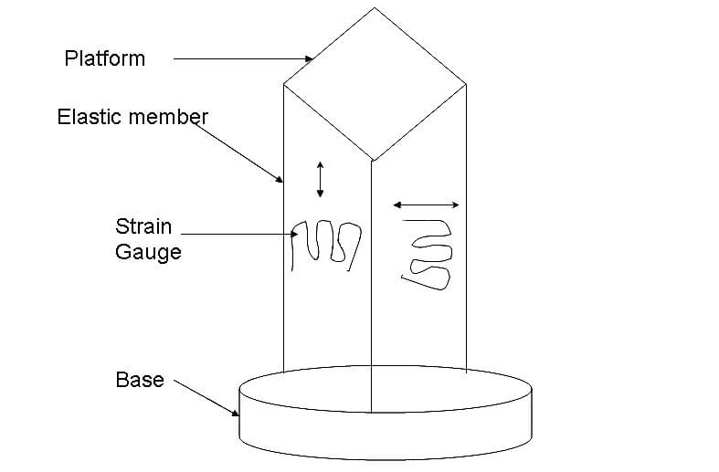
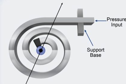
The figure shown below is the Load cell Construction Diagram.On applying load, the elastic member will deform or deflect.

Since the strain gauge is attached to the elastic member, strain gauge may elongate or compress due to tension. This varies its length and in turn its resistance varies.

By measuring the variation in the resistance of the strain gauge, the applied load can be calculated.

Construction of Load Cell

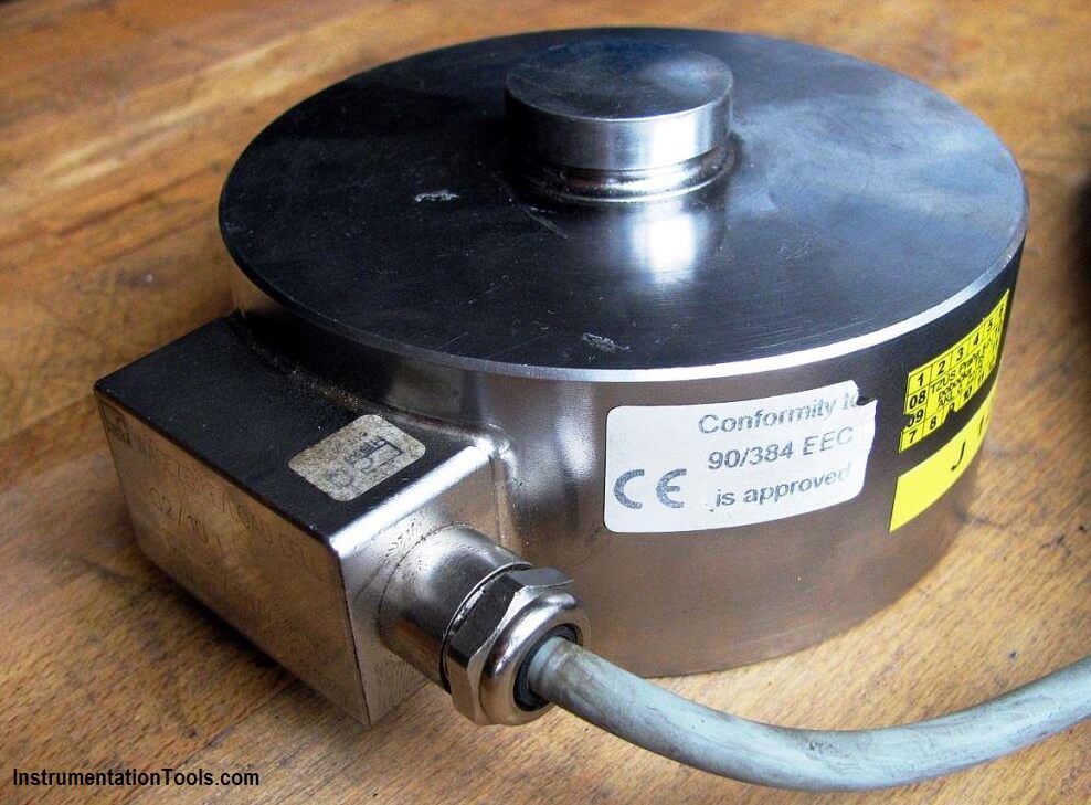
The figure shows the construction of the tensile compressive cell which is a cylinder. This arrangement uses four strain gauges, each mounted at 90 to each other.

On applying load, due to tension, two of the strain gauges experience elongation or tensile stress while the other two are subjected to compression.

Load Cell Bridge Circuit

Since the load cell is cylinder, an axial compressive load causes a negative strain in vertical gauges and a positive strain in the circumferential gauges.

The two strains are not equal. By using bridge circuit, resistance of the strain gauge is measured and hence the unknown applied load.

Types of Load Cells

The Load Cell Types are classified based on three criteria. They are

  • Working principle of a load cell
  • Construction of Load Cell
  • Electrical Properties of the load cell

Based on the Working Principle of the Load Cell

  • Compression Principle
  • Tensile based Working
  • Universal
  • Hollow
  • Shear Based

Based on the Construction of the Load Cell

  • S type Construction load cell
  • Load Button types
  • Single ended shear beam
  • Double ended shear beam Load cell
  • Single column and Multi Column load cell
  • Pancake Load cell
  • Diaphragm/membrane
  • Torsion Ring Load cell

Based on the Electrical Properties of the Load cell

  • Analog and Digital property based load cell
  • Resistance and Capacitance Based
  • Piezoelectric and Wireless Based Load cell
Don't Miss Our Updates
Be the first to get exclusive content straight to your email.
We promise not to spam you. You can unsubscribe at any time.
Invalid email address
You've successfully subscribed !

Continue Reading

Identify the Pressure Gauge Error
What is Static Pressure Limit in DP Transmitter ?
Pressure Gauges with Bourdon Tube Principle
How Measurement Span of Pressure Gauge Could be Changed?
Pressure Transmitter Manifolds
Basics of Differential Pressure Transmitters
Share This Article
Facebook Whatsapp Whatsapp LinkedIn Copy Link
Share
1 Comment
  • umesh Singh says:
    December 26, 2020 at 6:28 pm

    Meaning of RTR, Ln, Lt, Ld, Re AND Rain case of load cell

    Reply

Leave a Reply Cancel reply

Your email address will not be published. Required fields are marked *

Stay Connected

128.3kFollowersLike
69.1kFollowersFollow
208kSubscribersSubscribe
38kFollowersFollow

Categories

Explore More

Scaling Sensor Output to Engineering Units
Differential Pressure Switch Principle
Pressure Gauge Water Traps and Pigtail Siphons
Double Block and Bleed Valves Opening or Closing Sequence
Pressure Gauges with Diaphragm Sensor Principle
Impulse Line Purging and Close Coupling of Instruments
Magnehelic Gauge Calibration
Why are Impulse Lines often Installed in a Sloping Manner?

Keep Learning

pressure transmitter calibration setup

Questions on Pressure Transmitter Calibration Setup

Three Valve Manifold

3 Valve Manifold Operation

What is Capillary Tubing

What is Capillary Tubing? – Advantages and Disadvantages

Strain Gauge Pressure Sensor Principle

Strain Gauge Pressure Sensor Principle

5 Valve manifold

5 Valve Manifold Operation

Types of Pressure

Types of Pressure – Instrument Questions and Answers

DeadWeight Tester

DeadWeight Tester Questions

Pressure Detection Circuit

Pressure Detection Circuit

Learn More

Practical Process Control System Questions

Process Control Loop Testing

Three Phase AC Generators

Three Phase AC Generators

4-20mA Transmitters Easy Calculations

4-20mA Transmitters Calculations

transistor-terminals

Basics of Transistors

PID control block located in fieldbus transmitter

Foundation Fieldbus Device addressing

Streams After Electrical Engineering Graduation

Streams After Electrical Engineering Graduation

Mass Flow Calculations of flow measurement

Mass Flow Calculations

Industrial Automation Acronyms

111 Industrial Automation Acronyms Questions and Answers

Follow US
All rights reserved. Reproduction in whole or in part without written permission is prohibited.
Welcome Back!

Sign in to your account

Username or Email Address
Password

Lost your password?