In Siemens S7 300 CPUs, there is a series of LED lights with different colors which shows us the modes, status, and errors of the PLC.
S7 300 LED Errors
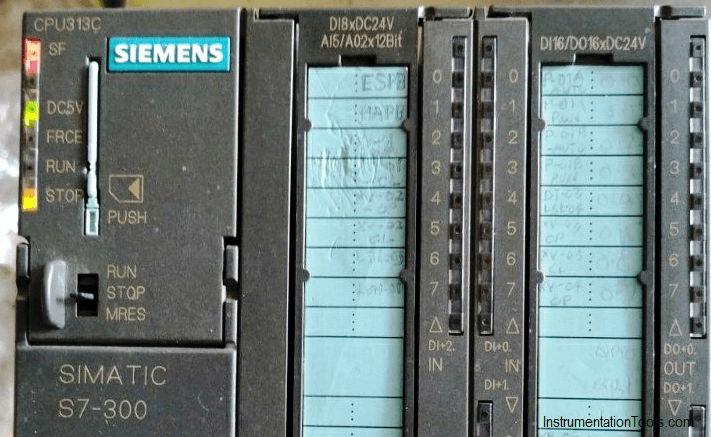
SF
System fault: it indicates there is an error in the system, this error could be software error like an error in programming or hardware error like a power loss of one of the input modules
Color: Steady Red
BF
Bus Fault: it indicates that there is an error in the system network, like a bad contact in one of the communication connectors, or there is an overlap between the addresses in the network
Color: Steady Red
MAINT
Maintenance: where ever this indicator energized this means that the CPU is not working anymore and needs a service, but this is rarely happening.
Color: Steady yellow
DC5V
This led indicates that there is a 24 Volt DC provided to the CPU.
Color: Steady Green
FRCE
Force: it indicates that at least one of the PLC inputs or outputs is forced to on or off.
Color: Steady yellow
Run
Run mode is on whenever the CPU is working properly without any troubles, and flashes in the startup of the CPU.
Color: Steady Green
STOP
a.
When the CPU is in STOP mode or there is a software/hardware error.
Color: Steady yellow
b.
For a memory reset request when inserting the memory card.
Color: Yellow flashes slowly
c.
When the memory reset is being carried out.
Color: Yellow flashes quickly
Author: Karim Ali Anwar
If you liked this article, then please subscribe to our YouTube Channel for PLC and SCADA video tutorials.
You can also follow us on Facebook and Twitter to receive daily updates.
Read Next:
- Problems with TON Timer
- Analogy of Ohm’s Law
- As-found and As-left Calibration
- Workstation Healthiness Checks
- Programmable Logic Controller


Hello Karim, thank you very much for your explanation about the S7 300. Have a great day.
What if all the indications flashes at a time? Can anyone explain me about this?
APPRECITED WITH THE UPDATE ON S7-300-LED ERRORS.
THANK YOU.
In CPU 315 2PN/DP
if all indicator LED light same time glowing with out blinking what is the problem??
Thank you