Inst ToolsInst ToolsInst Tools
  • Courses
  • Videos
  • Q & A
    • Interview
      • Instrumentation
      • Electronics
      • Electrical
      • Practical Questions
    • MCQ
      • Instrumentation MCQ
      • Electrical MCQ
      • Electronics MCQ
      • Control Systems MCQ
      • Analog Electronics MCQ
      • Digital Electronics MCQ
      • Power Electronics MCQ
      • Microprocessor MCQ
      • Multiple Choice Questions
  • EE
    • Electronics
      • Electronics Q & A
      • Electronic Basics
      • Electronic Devices & Circuits
      • Electronics Animation
      • Digital Electronics
    • Electrical
      • Electrical Basics
      • Electrical Q & A
      • Power Electronics
      • Electrical Machines
      • Electrical Animation
      • Power Systems
      • Switchgear & Protection
      • Transmission & Distribution
  • Measure
    • Control Valves
    • Calibration
    • Temperature
    • Pressure
    • Flow
    • Level
    • Analyzers
    • Switches
    • Vibration
    • Solenoid Valve
  • Control
    • PLC Tutorials
    • Control Systems
    • Safety Instrumented System (SIS)
    • Communication
    • Fire & Gas System
  • More
    • Design
    • Tools
    • Animation
    • Basics
    • Formulas
    • Standards
    • TextBooks
    • Common
    • Software
    • Excel Tools
    • Erection & Commissioning
    • Process Fundamentals
    • Videos
    • Books
Search
All rights reserved. Reproduction in whole or in part without written permission is prohibited.
Reading: Capacitor Filter Operation
Share
Notification Show More
Font ResizerAa
Inst ToolsInst Tools
Font ResizerAa
  • Courses
  • PLC Tutorials
  • Control Systems
Search
  • Courses
  • Videos
  • Q & A
    • Interview
    • MCQ
  • EE
    • Electronics
    • Electrical
  • Measure
    • Control Valves
    • Calibration
    • Temperature
    • Pressure
    • Flow
    • Level
    • Analyzers
    • Switches
    • Vibration
    • Solenoid Valve
  • Control
    • PLC Tutorials
    • Control Systems
    • Safety Instrumented System (SIS)
    • Communication
    • Fire & Gas System
  • More
    • Design
    • Tools
    • Animation
    • Basics
    • Formulas
    • Standards
    • TextBooks
    • Common
    • Software
    • Excel Tools
    • Erection & Commissioning
    • Process Fundamentals
    • Videos
    • Books
Follow US
All rights reserved. Reproduction in whole or in part without written permission is prohibited.
Inst Tools > Blog > Electronic Devices & Circuits > Capacitor Filter Operation

Capacitor Filter Operation

Last updated: September 27, 2016 3:52 pm
Editorial Staff
Electronic Devices & Circuits
No Comments
Share
2 Min Read
SHARE

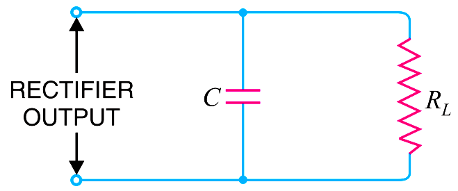
Capacitor filter.  Fig. shows a typical capacitor filter circuit.  It consists of a capacitor C placed across the rectifier output in parallel with load RL. The pulsating direct voltage of the rectifier is applied across the capacitor. As the rectifier voltage increases, it charges the capacitor and also supplies current to the load.

Capacitor Filter Operation

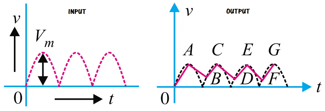
At the end of quarter cycle [Point A in Fig.], the capacitor is charged to the peak value Vm of the rectifier voltage. Now, the rectifier voltage starts to decrease. As this occurs, the capacitor discharges through the load and voltage across it (i.e. across parallel combination of R–C) decreases as shown by the line AB in Fig. The voltage across load will decrease only slightly because immediately the next voltage peak comes and recharges the capacitor. This process is repeated again and again and the output voltage waveform becomes ABCDEFG.  It may be seen that very little ripple is left in the output.  Moreover, output voltage is higher as it remains substantially near the peak value of rectifier output voltage.

capacitor-filter-output

how-capacitor-filter-works

The capacitor filter circuit is extremely popular because of its low cost, small size, little weight and good characteristics. For small load currents, this type of filter is preferred.
Don't Miss Our Updates
Be the first to get exclusive content straight to your email.
We promise not to spam you. You can unsubscribe at any time.
Invalid email address
You've successfully subscribed !

Recommended Articles

CRT Fluorescent Screen
Seven Segment Display Working Principle
Diodes Voltage Tripler
Basics of Amplifiers Interview Questions
Photodiode Working Principle
Bipolar Junction Transistor Construction
Share This Article
Facebook Whatsapp Whatsapp LinkedIn Copy Link
Share
Leave a Comment

Leave a Reply Cancel reply

Your email address will not be published. Required fields are marked *

Stay Connected

128.3kFollowersLike
69.1kFollowersFollow
208kSubscribersSubscribe
38kFollowersFollow

Categories

Recent Comments

  • William Snyder on Top Non-PLC Certification Courses for Automation Professionals
  • Kamli on Top Free PLC Software
  • Guifty Shimica on Top Non-PLC Certification Courses for Automation Professionals
  • Guifty Shimica on Top Non-PLC Certification Courses for Automation Professionals

Related Articles

Insulators, Conductors and Semiconductors

How a Multi Color LED Works

How a Multi Color LED Works ?

Transistors Questions & Answers

Transistors Questions & Answers

example-of-KCL

What is Kirchhoff’s Current Law

Transistor Amplifier Working Principle

reverse-biased varactor diode

Varactor Diode Operation

Optoisolator Working Principle

Optoisolator Working Principle

Applications of Photo diodes

Applications of Photo diodes

More Articles

Electrical Switchgear & Protection Interview Questions

Electrical Switchgear & Protection Interview Questions

Sequential Timer Control of Lamps

Schneider PLC Example: Control Lamps Sequences

Cables Sheath Material

Instrument Cables Sheath Material

How to Filter Digital and Analog Inputs in a PLC

How to Filter Digital and Analog Inputs in a PLC?

LBB protection relay

What is the LBB Protection Relay? (Local Breaker Backup)

Opposite Acting Control Valves Application

PLC Ladder Logic for Opposite Acting Control Valves Application

pH Analyzer Calibration and Troubleshooting

Troubleshooting pH Analyzer Common Problems

Single Phase Half-controlled Rectifier RL Load With FD

Phase-Controlled Half-Wave Rectifier With Freewheeling Diode

Follow US
All rights reserved. Reproduction in whole or in part without written permission is prohibited.
Welcome Back!

Sign in to your account

Username or Email Address
Password

Lost your password?