Inst ToolsInst ToolsInst Tools
  • Ask
  • Courses
  • Videos
  • Q & A
    • Interview
      • Instrumentation
      • Electronics
      • Electrical
      • Practical Questions
    • MCQ
      • Instrumentation MCQ
      • Electrical MCQ
      • Electronics MCQ
      • Control Systems MCQ
      • Analog Electronics MCQ
      • Digital Electronics MCQ
      • Power Electronics MCQ
      • Microprocessor MCQ
      • Multiple Choice Questions
  • EE
    • Electronics
      • Electronics Q & A
      • Electronic Basics
      • Electronic Devices & Circuits
      • Electronics Animation
      • Digital Electronics
    • Electrical
      • Electrical Basics
      • Electrical Q & A
      • Power Electronics
      • Electrical Machines
      • Electrical Animation
      • Power Systems
      • Switchgear & Protection
      • Transmission & Distribution
  • Measure
    • Control Valves
    • Calibration
    • Temperature
    • Pressure
    • Flow
    • Level
    • Analyzers
    • Switches
    • Vibration
    • Solenoid Valve
  • Control
    • PLC Tutorials
    • Control Systems
    • Safety Instrumented System (SIS)
    • Communication
    • Fire & Gas System
  • More
    • Design
    • Tools
    • Animation
    • Basics
    • Formulas
    • Standards
    • TextBooks
    • Common
    • Software
    • Excel Tools
    • Erection & Commissioning
    • Process Fundamentals
    • Videos
    • Books
Search
All rights reserved. Reproduction in whole or in part without written permission is prohibited.
Reading: How to Draw a Schematic Diagram ?
Share
Notification Show More
Font ResizerAa
Inst ToolsInst Tools
Font ResizerAa
  • Courses
  • PLC Tutorials
  • Control Systems
Search
  • Ask
  • Courses
  • Videos
  • Q & A
    • Interview
    • MCQ
  • EE
    • Electronics
    • Electrical
  • Measure
    • Control Valves
    • Calibration
    • Temperature
    • Pressure
    • Flow
    • Level
    • Analyzers
    • Switches
    • Vibration
    • Solenoid Valve
  • Control
    • PLC Tutorials
    • Control Systems
    • Safety Instrumented System (SIS)
    • Communication
    • Fire & Gas System
  • More
    • Design
    • Tools
    • Animation
    • Basics
    • Formulas
    • Standards
    • TextBooks
    • Common
    • Software
    • Excel Tools
    • Erection & Commissioning
    • Process Fundamentals
    • Videos
    • Books
Follow US
All rights reserved. Reproduction in whole or in part without written permission is prohibited.
Inst Tools > Blog > Practical Questions > How to Draw a Schematic Diagram ?

How to Draw a Schematic Diagram ?

Last updated: September 2, 2017 4:54 am
Editorial Staff
Practical Questions
No Comments
Share
1 Min Read
SHARE

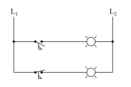
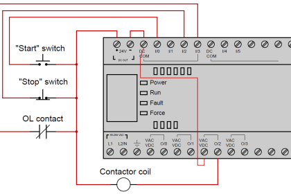
An alternative to the conventional schematic diagram in AC power control systems is the ladder diagram. In this convention, the “hot” and “neutral” power conductors are drawn as vertical lines near the edges of the page, with all loads and switch contacts drawn between those lines like rungs on a ladder:

Relay ladder diagram example

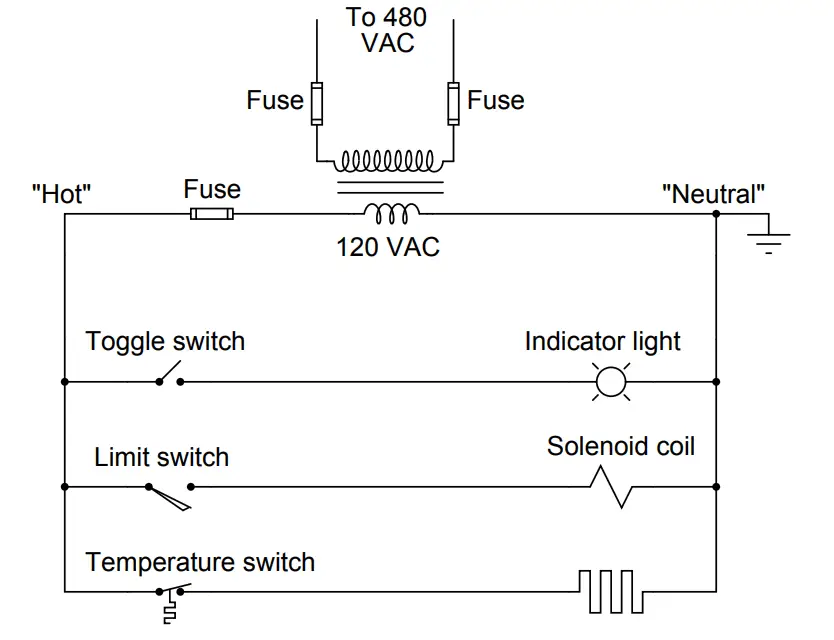
As you can see, the symbolism in ladder diagrams is not always the same as in electrical schematic diagrams. While some symbols are identical (the toggle switch, for instance), other symbols are not (the solenoid coil, for instance).

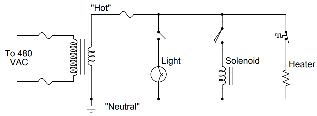
Re-draw this ladder diagram as a schematic diagram, translating all the symbols into those correct for schematic diagrams.

Answer :

Relay Schematic example

Credits : by Tony R. Kuphaldt – under CC BY 1.0

Don't Miss Our Updates
Be the first to get exclusive content straight to your email.
We promise not to spam you. You can unsubscribe at any time.
Invalid email address
You've successfully subscribed !
Programmable Logic Controller (PLC) Questions and Answers – 7
Analyze the Relay Circuit and Find the Status ?
LRV and URV of PT for Extreme Limits of Empty and Full
Thermocouple Terminal block Questions
Purge Type Level Transmitter Questions
Share This Article
Facebook Whatsapp Whatsapp LinkedIn Copy Link
Share
Leave a Comment

Leave a Reply Cancel reply

Your email address will not be published. Required fields are marked *

Stay Connected

128.3kFollowersLike
69.1kFollowersFollow
208kSubscribersSubscribe
38kFollowersFollow

Categories

Recent Comments

  • Kamli on Top Free PLC Software
  • Guifty Shimica on Top Non-PLC Certification Courses for Automation Professionals
  • Guifty Shimica on Top Non-PLC Certification Courses for Automation Professionals
  • MIHARITSOA Aina Sitraka on Top Non-PLC Certification Courses for Automation Professionals

Related Articles

Calculate Amount of Weight Indicated by the Scale

Calculate Amount of Weight Indicated by the Scale

Electronic Pressure Sensor with Bourdon Tube and LVDT

Electronic Pressure Sensor with Bourdon Tube and LVDT

PSV lift pressure

Calculate PSV Lift Pressure

Programmable Logic Controller (PLC) Questions and Answers

Programmable Logic Controller (PLC) Questions and Answers – 2

Dip Tube Type Level System

Questions on Dip Tube Type Level System

Foxboro model 13 DP transmitter

Re-calibrate the Foxboro DP Pneumatic Transmitter

Simple Pressure Repeater

Simple Pressure Repeater

process conditions, Find out the Circuit Components Status

As per Process Conditions, Find out the Circuit Components Status ?

More Articles

Optimal Control Systems

The Infinite Time Regulator Problem

Calibration Sheet

Calibration : Up-tests and Down-tests

Ball Valve Pictures

How Ball Valves Work ?

Microprocessors Objective Questions

Microprocessors Objective Questions

Dependent Voltage Source

Dependent Voltage Source

Fire and Gas System

Types of Fire and Gas Detectors

Digital Electronics Multiple Choice Questions

Memory Devices Objective Questions – Part 5

Free Allen Bradley PLC Training Course

Free Allen Bradley PLC Ladder Logic Training Course

Follow US
All rights reserved. Reproduction in whole or in part without written permission is prohibited.
Welcome Back!

Sign in to your account

Username or Email Address
Password

Lost your password?