Inst ToolsInst ToolsInst Tools
  • Courses
  • Automation
    • PLC
    • Control System
    • Safety System
    • Communication
    • Fire & Gas System
  • Instrumentation
    • Design
    • Pressure
    • Temperature
    • Flow
    • Level
    • Vibration
    • Analyzer
    • Control Valve
    • Switch
    • Calibration
    • Erection & Commissioning
  • Interview
    • Instrumentation
    • Electrical
    • Electronics
    • Practical
  • Q&A
    • Instrumentation
    • Control System
    • Electrical
    • Electronics
    • Analog Electronics
    • Digital Electronics
    • Power Electronics
    • Microprocessor
  • Request
Search
  • Books
  • Software
  • Projects
  • Process
  • Tools
  • Basics
  • Formula
  • Power Plant
  • Root Cause Analysis
  • Electrical Basics
  • Animation
  • Standards
  • 4-20 mA Course
  • Siemens PLC Course
Reading: Gage and Absolute Pressure Transmitters Principle
Share
Font ResizerAa
Inst ToolsInst Tools
Font ResizerAa
  • Courses
  • Design
  • PLC
  • Interview
  • Control System
Search
  • Courses
  • Automation
    • PLC
    • Control System
    • Safety System
    • Communication
    • Fire & Gas System
  • Instrumentation
    • Design
    • Pressure
    • Temperature
    • Flow
    • Level
    • Vibration
    • Analyzer
    • Control Valve
    • Switch
    • Calibration
    • Erection & Commissioning
  • Interview
    • Instrumentation
    • Electrical
    • Electronics
    • Practical
  • Q&A
    • Instrumentation
    • Control System
    • Electrical
    • Electronics
    • Analog Electronics
    • Digital Electronics
    • Power Electronics
    • Microprocessor
  • Request
Follow US
All rights reserved. Reproduction in whole or in part without written permission is prohibited.
Inst Tools > Blog > Pressure Measurement > Gage and Absolute Pressure Transmitters Principle

Gage and Absolute Pressure Transmitters Principle

Last updated: May 15, 2019 5:47 pm
Editorial Staff
Pressure Measurement
1 Comment
Share
3 Min Read
SHARE

Gage and Absolute Pressure Transmitters :

Sensor Design for Gage Pressure Measurement

gage pressure transmitter principle

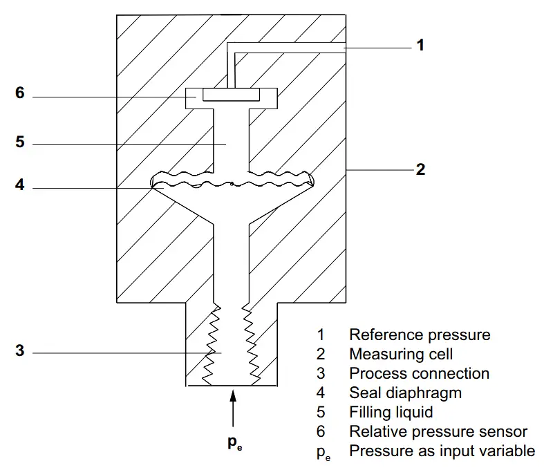
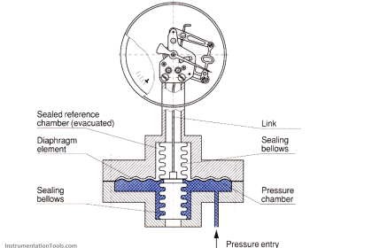
The input pressure (pe) is transferred to the gage pressure sensor (6) via the seal diaphragm (4) and the filling liquid (5), displacing its measuring diaphragm.

The displacement changes the resistance value of the four piezo resistors in the measuring diaphragm in a bridge circuit.

The change in the resistance causes a bridge output voltage proportional to the input pressure.

The transmitters with spans ≤ 63 bar measure the input pressure against atmosphere, those with spans ≥ 160 bar against vacuum.

Sensor Design for Absolute Pressure Measurement

absolute pressure transmitter principle

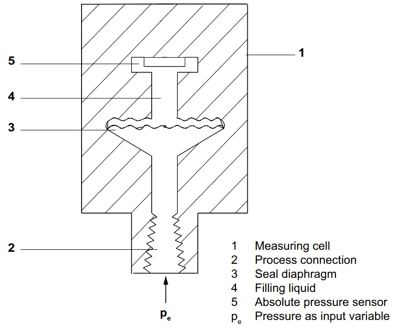
The input pressure (pe) is transferred to the absolute pressure sensor (5) via the seal diaphragm (3) and the filling liquid (4), displacing its measuring diaphragm.

The displacement changes the resistance value of the four piezo resistors in the measuring diaphragm in a bridge circuit.

The change in the resistance causes a bridge output voltage proportional to the input pressure.

Pressure Transmitter Block Diagram :

Pressure Transmitter Working Principle

Pressure Transmitter Parts

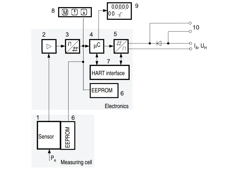
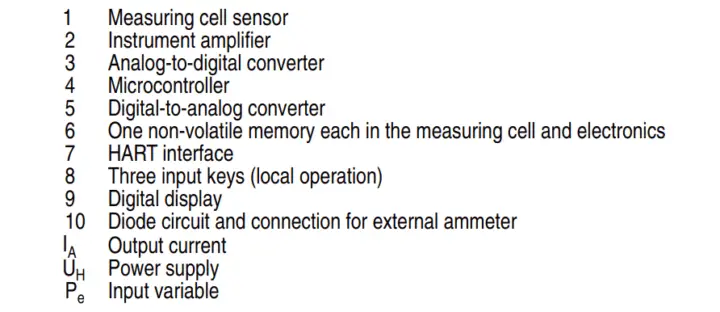
The input pressure is converted into an electrical signal by the sensor (1). This signal is amplified by the measuring amplifier (2) and digitalized in an analog to digital converter (3). The digital signal is analyzed in a microcontroller (4) and corrected with regard to linearity and thermal characteristics.

In a digital to analog converter (5) it is then converted into the output current of 4 to 20 mA. A diode circuit provides reverse voltage protection. You can make an uninterrupted current measurement with a low ohm ammeter at the connection (10).

The data specific to the measuring cell, the electronic data and parameter settings are stored in two non-volatile memories (6). The first memory is linked with the measuring cell, the second with the electronics.

The buttons (8) can be used to call up individual functions, socalled modes. If you have a device with a digital display (9), you can use this to track mode settings and other messages. The basic mode settings can be changed with a computer via the HART modem (7).

Reference : Siemens Manual, Image Credits : Siemens

Don't Miss Our Updates
Be the first to get exclusive content straight to your email.
We promise not to spam you. You can unsubscribe at any time.
Invalid email address
You've successfully subscribed !

Continue Reading

DeadWeight Tester Questions
Information on the Pressure Gauge Dial
Metal Foil Strain Gauge Principle
Types of Pressure Measuring Scales
Why are Impulse Lines often Installed in a Sloping Manner?
What are Pressure Sensing Lines? – Causes of Errors in Measurement
Share This Article
Facebook Whatsapp Whatsapp LinkedIn Copy Link
Share
1 Comment
  • Jitendra meena says:
    August 26, 2017 at 1:33 pm

    Very useful information.
    But sir how to identify that it is Rosemont gauge pressure or absolute pressure transmitter in 2051c series.

    Reply

Leave a Reply Cancel reply

Your email address will not be published. Required fields are marked *

Stay Connected

128.3kFollowersLike
69.1kFollowersFollow
210kSubscribersSubscribe
38kFollowersFollow

Categories

Explore More

Pressure Transmitter Manifolds
Pressure Switch Calibration Procedure
Types of Manometers
Difference between Axial and Radial Diaphragm Seal Connection?
Uncertainty Calculations of Pressure Calibration
Well Manometer Principle
Pressure Transmitter Calibration Procedure
Bourdon Tube Pressure Gauge Advantages and Disadvantages

Keep Learning

U tube Manometer Working

Basics of Pressure

Pressure Gauge Calibration according to Standard DKD-R-6-1

Pressure Gauge Calibration according to Standard DKD-R-6-1

Helix and Spiral Tubes - Pressure Sensor

Helix and Spiral Tubes – Pressure Sensor

Semi Conductor or Piezo Resistive Strain Gauge Principle

Semi Conductor or Piezo Resistive Strain Gauge Principle

Pressure Sensor Temperature Effects

Temperature Compensation for Pressure Measurement

Diaphragm seal for pressure measurement device

When to use a Diaphragm Seal?

Pressure Transmitter Troubleshooting Tips

Pressure Transmitter Troubleshooting Tips

piping for a Different pressure flow transmitter

Impulse Piping standards for Field instruments

Learn More

Differential Pressure Transmitters Static Pressure

What is Static Pressure Limit in DP Transmitter ?

Variable-speed motor controls

Variable Motor Speed Control

Landline Telemetry Objective Questions

Landline Telemetry Objective Questions

PLC Logic - Control Spray Nozzle, Fans, and Puncher

PLC Logic: Control Spray Nozzle, Fans, and Puncher

Parts of PLC

Parts of PLC

Sources of Static Grounding and Methods to Control

Sources of Static Grounding and Methods to Control

PID Controller Tunning Manually

PID Controller Parameters Tuning Manually

Venturi Flow Theory

Facts About Orifice Flow Meters

Menu

  • About
  • Privacy Policy
  • Copyright

Quick Links

  • Learn PLC
  • Helping Hand
  • Part Time Job

YouTube Subscribe

Follow US
All rights reserved. Reproduction in whole or in part without written permission is prohibited.
Welcome Back!

Sign in to your account

Username or Email Address
Password

Lost your password?