A tap changer is a device fitted to power transformers for regulation of the output voltage to required levels. This is normally achieved by changing the ratios of the transformers on the system by altering the number of turns in one winding of the appropriate transformer/s. Supply authorities are under obligation to their customers to maintain the supply voltage between certain limits. Tap changers offer variable control to keep the supply voltage within these limits. About 96% of all power transformers today above 10MVA incorporate on load tap changers as a means of voltage regulation.
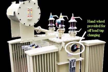
Tap changers can be on load or off load. On load tap changers generally consist of a diverter switch and a selector switch operating as a unit to effect transfer current from one voltage tap to the next. It was more than 60 years ago on load tap changers were introduced to power transformers as a means of on load voltage control.
Tap changers possess two fundamental features:
(a) Some form of impedance is present to prevent short circuiting of the tapped section,
(b) A duplicate circuit is provided so that the load current can be carried by one circuit whilst switching is being carried out on the other.
The impedance mentioned above can either be resistive or reactive. The tap changer with a resistive type of impedance uses high speed switching, whereas the reactive type uses slow moving switching. High speed resistor switching is now the most popular method used worldwide, and hence it is the method that is reviewed in this report.
The tapped portion of the winding may be located at one of the following locations, depending upon the type of winding:
(a) At the line end of the winding;
(b) In the middle of the winding;
(c) At the star point.
The most common type of arrangements is the last two. This is because they give the least electrical stress between the tap changer and earth; along with subjecting the tapings to less physical and electrical stress from fault currents entering the line terminals. At lower voltages the tap changer may be located at either the low voltage or high voltage windings.
Tap changers can be connected to the primary or secondary side windings of the transformer depending on:
– Current rating of the transformer
– Insulation levels present
– Type of winding within the transformer (eg. Star, delta or autotransformer)
– Position of tap changer in the winding
– Losses associated with different tap changer configurations eg. Coarse tap or reverse winding
– Step voltage and circulating currents
– Cost
– Physical size
The Consequences Of Transformer Failure
Transformers are one of the more expensive pieces of equipment used in a power system, and the potential consequences of failure can be quite damaging. This has been shown in the past with the political and media attention surrounding blackouts at various locations around the world. Within Australia and New Zealand, the largest cost transformer failures have occurred due to internal winding faults, faulty load tap changers, and failed winding accessories respectively.
Failure of winding accessories includes loose coil clamping bolts, together with internal winding faults and faulty tap changers. These failures affected on average ten transformers per year during the period 1975 to 1995, incurring repair costs of at least $600,000 per year, together with other associated costs. For example, with several elements drawn from an Australian case study and through discussion with engineers at Pacific Power’s Advanced Technical Center, the cost of a generator unit transformer failing has been conservatively estimated at $5.4M. This figure was considered conservative because there are many other factors that could be added on to this figure that are difficult to determine. It is interesting to note the root of these failures appear to have been predominantly design and manufacturing flaws.
Current Maintenance Strategies of Transformer Tap Changers
During the past years and after a number of visits, meetings, lectures and training courses, the conclusion has been reached that proper organization and execution of OLTC maintenance is found only in very few cases.
The frequency of maintenance to on load tap changers is dependent on the condition of the diverter switch and the necessity to maintain the motor drive unit. Maintenance of the diverter switch should be carried out on a cyclic basis, but on transformers where frequency of tap change is high, maintenance may be necessary before the cyclic maintenance becomes due. A certain period should not be exceeded between inspections. When considering inspection periods, serious consideration should be given to the breaking of circulating current which in some cases may exceed the load current.
The diverter switch and tap selector is the only internal moving parts in a transformer. The diverter switch does the entire on load making and breaking of currents, whereas the tap selector preselects the tap to which the diverter switch will transfer the load current. The tap selector operates off load and therefore needs no maintenance. However experience has shown that in some circumstances inspection of selector switches becomes necessary where contacts become misaligned or contact braids in fact fatigueandbreak.
The next segment is a list taken from on what should be carried out during tap changer maintenance;
– Replace contacts in older type tap changers. Modern tap changers rarely require contact replacement; this depends on the characteristics of the tap changer in question. The frequency of diverter switch and motor drive unit inspections can usually be obtained from manufacturer manuals or previous maintenance experience.
– Measuring and recording contact consumption during inspection will give a reasonably accurate life expectancy of the contacts at that present load condition. Therefore this should be done on a regular basis.
– Transition resistors should be checked for continuity and value as an open circuited resistor can result in excessive contact wear.
– Need to equalize rotation lag between the diverter switch and the motor drive unit to ensure minimum spring energisation in the energy accumulator springs.
– The function of relays, interlocks, limit switches and switches should be checked as well as remote indication of tap position.
– Drive shafts and gearboxes must be inspected for radial and axial wear. A large percentage of tap change failures are as a result of drive shaft faults.
– Replace transformer oil with clean, dry oil. Cleaning is only carried out with transformer oil not solvents. Carbon and copper deposits are generally found on horizontal surfaces of the diverter switch as small convection currents in the oil are established each tap change. This results in the carbon being deposited on top of the diverter.