Inst ToolsInst ToolsInst Tools
  • Ask
  • Courses
  • Videos
  • Q & A
    • Interview
      • Instrumentation
      • Electronics
      • Electrical
      • Practical Questions
    • MCQ
      • Instrumentation MCQ
      • Electrical MCQ
      • Electronics MCQ
      • Control Systems MCQ
      • Analog Electronics MCQ
      • Digital Electronics MCQ
      • Power Electronics MCQ
      • Microprocessor MCQ
      • Multiple Choice Questions
  • EE
    • Electronics
      • Electronics Q & A
      • Electronic Basics
      • Electronic Devices & Circuits
      • Electronics Animation
      • Digital Electronics
    • Electrical
      • Electrical Basics
      • Electrical Q & A
      • Power Electronics
      • Electrical Machines
      • Electrical Animation
      • Power Systems
      • Switchgear & Protection
      • Transmission & Distribution
  • Measure
    • Control Valves
    • Calibration
    • Temperature
    • Pressure
    • Flow
    • Level
    • Analyzers
    • Switches
    • Vibration
    • Solenoid Valve
  • Control
    • PLC Tutorials
    • Control Systems
    • Safety Instrumented System (SIS)
    • Communication
    • Fire & Gas System
  • More
    • Design
    • Tools
    • Animation
    • Basics
    • Formulas
    • Standards
    • TextBooks
    • Common
    • Software
    • Excel Tools
    • Erection & Commissioning
    • Process Fundamentals
    • Videos
    • Books
Search
All rights reserved. Reproduction in whole or in part without written permission is prohibited.
Reading: Why Damper windings used in synchronous motors
Share
Notification Show More
Font ResizerAa
Inst ToolsInst Tools
Font ResizerAa
  • Courses
  • PLC Tutorials
  • Control Systems
Search
  • Ask
  • Courses
  • Videos
  • Q & A
    • Interview
    • MCQ
  • EE
    • Electronics
    • Electrical
  • Measure
    • Control Valves
    • Calibration
    • Temperature
    • Pressure
    • Flow
    • Level
    • Analyzers
    • Switches
    • Vibration
    • Solenoid Valve
  • Control
    • PLC Tutorials
    • Control Systems
    • Safety Instrumented System (SIS)
    • Communication
    • Fire & Gas System
  • More
    • Design
    • Tools
    • Animation
    • Basics
    • Formulas
    • Standards
    • TextBooks
    • Common
    • Software
    • Excel Tools
    • Erection & Commissioning
    • Process Fundamentals
    • Videos
    • Books
Follow US
All rights reserved. Reproduction in whole or in part without written permission is prohibited.
Inst Tools > Blog > Electrical Machines > Why Damper windings used in synchronous motors

Why Damper windings used in synchronous motors

Last updated: April 24, 2016 6:07 pm
Editorial Staff
Electrical Machines
No Comments
Share
2 Min Read
SHARE

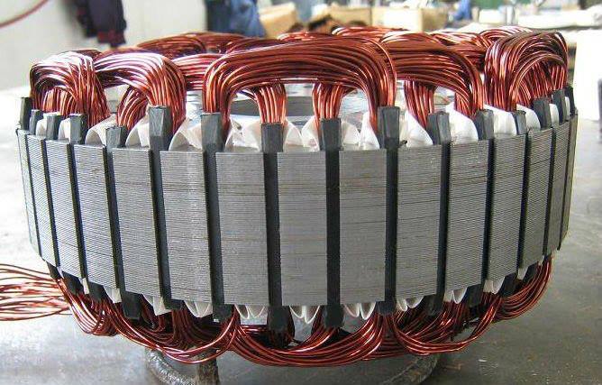
Synchronous motors are not self starting machines. These machines are made self starting by providing a special winding in the rotor poles, known as damper winding or squirrel cage windings. The damper winding consists of short circuited copper bars embedded in the the face of the rotor poles

When an ac supply is provided to stator of a 3-phase synchronous motor, stator winding produces rotating magnetic field. Due to the damper winding present in the rotor winding of the synchronous motor, machine starts as induction motor (Induction machine works on the principle of induction. Damper windings in synchronous motor will carryout the same task of induction motor rotor windings. Therefore due to damper windings synchronous motor starts as induction motor and continue to accelerate).

The exciter for synchronous motor moves along with rotor. When the motor attains about 95% of the synchronous speed, the rotor windings is connected to exciter terminals and the rotor is magnetically locked by the rotating magnetic field of stator and it runs as a synchronous motor.

Why Damper windings used in synchronous motors

Functions of Damper Windings:

  • Damper windings helps the synchronous motor to start on its own (self starting machine) by providing starting torque
  • By providing damper windings in the rotor of synchronous motor “Hunting of machine”can be suppressed.When there is change in load, excitation or change in other conditions of the systems rotor of the synchronous motor will oscillate to and fro about an equilibrium position. At times these oscillations becomes more violent and resulting in loss of synchronism of the motor and comes to halt
Don't Miss Our Updates
Be the first to get exclusive content straight to your email.
We promise not to spam you. You can unsubscribe at any time.
Invalid email address
You've successfully subscribed !
Difference between Permanent Magnet BLDC and DC Motor
6.6kV HV Induction motor Protection
Metering Pumps
What is a Transformer Tap Changer
Star to Delta and Delta to Star Conversion Formula
Share This Article
Facebook Whatsapp Whatsapp LinkedIn Copy Link
Share
Leave a Comment

Leave a Reply Cancel reply

Your email address will not be published. Required fields are marked *

Stay Connected

128.3kFollowersLike
69.1kFollowersFollow
208kSubscribersSubscribe
38kFollowersFollow

Categories

Recent Comments

  • Kamli on Top Free PLC Software
  • Guifty Shimica on Top Non-PLC Certification Courses for Automation Professionals
  • Guifty Shimica on Top Non-PLC Certification Courses for Automation Professionals
  • MIHARITSOA Aina Sitraka on Top Non-PLC Certification Courses for Automation Professionals

Related Articles

Synchronous Motor Is Not Self Starting?

Distribution transformer

Types of Transformers

Why rating of Synchronous Generators and Alternators in MVA or KVA

DC Motor Applications in Industries

Induction Motor Operating Characteristics

Why Armature is placed on Stator for Synchronous machines

Applications of Synchronous Motors

What is a transformer tap changer?

More Articles

DP transmitter Errors

DP Transmitter Calibration Errors

Digital Electronics Multiple Choice Questions

BCD Adder Objective Questions

Types of Resistors

Types of Resistors

Valve-Kv-Sizing-Calculator

Valve Kv Sizing Calculator

Control Loop

What is a Control Loop ?

Single Beam and Double Beam Instruments

Single Beam and Double Beam Instruments

Constant Torque Load of Electrical Motor

Types of Motor Loads – Constant & Variable Torque, Horsepower

Orifice Beta

Why is Orifice Beta in between 0.3 to 0.7?

Follow US
All rights reserved. Reproduction in whole or in part without written permission is prohibited.
Welcome Back!

Sign in to your account

Username or Email Address
Password

Lost your password?