Inst ToolsInst ToolsInst Tools
  • Courses
  • Automation
    • PLC
    • Control System
    • Safety System
    • Communication
    • Fire & Gas System
  • Instrumentation
    • Design
    • Pressure
    • Temperature
    • Flow
    • Level
    • Vibration
    • Analyzer
    • Control Valve
    • Switch
    • Calibration
    • Erection & Commissioning
  • Interview
    • Instrumentation
    • Electrical
    • Electronics
    • Practical
  • Q&A
    • Instrumentation
    • Control System
    • Electrical
    • Electronics
    • Analog Electronics
    • Digital Electronics
    • Power Electronics
    • Microprocessor
  • Request
Search
  • Books
  • Software
  • Projects
  • Process
  • Tools
  • Basics
  • Formula
  • Power Plant
  • Root Cause Analysis
  • Electrical Basics
  • Animation
  • Standards
  • 4-20 mA Course
  • Siemens PLC Course
Reading: Laws of Thermocouples
Share
Font ResizerAa
Inst ToolsInst Tools
Font ResizerAa
  • Courses
  • Design
  • PLC
  • Interview
  • Control System
Search
  • Courses
  • Automation
    • PLC
    • Control System
    • Safety System
    • Communication
    • Fire & Gas System
  • Instrumentation
    • Design
    • Pressure
    • Temperature
    • Flow
    • Level
    • Vibration
    • Analyzer
    • Control Valve
    • Switch
    • Calibration
    • Erection & Commissioning
  • Interview
    • Instrumentation
    • Electrical
    • Electronics
    • Practical
  • Q&A
    • Instrumentation
    • Control System
    • Electrical
    • Electronics
    • Analog Electronics
    • Digital Electronics
    • Power Electronics
    • Microprocessor
  • Request
Follow US
All rights reserved. Reproduction in whole or in part without written permission is prohibited.
Inst Tools > Blog > Temperature Measurement > Laws of Thermocouples

Laws of Thermocouples

Last updated: November 21, 2017 3:53 am
Editorial Staff
Temperature Measurement
No Comments
Share
3 Min Read
SHARE

The following empirically derived thermocouple laws, are useful to understand, diagnose and utilise thermocouples.

a) Law of homogeneous circuits

If two thermocouple junctions are at T1 and T2, then the thermal emf generated is independent and unaffected by any temperature distribution along the wires.

Law of homogeneous circuits

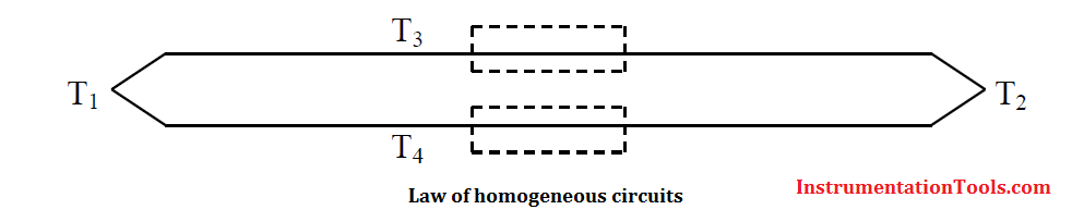
In above Figure, a thermocouple is shown with junction temperatures at T1 and T2. Along the thermocouple wires, the temperature is T3 and T4. The thermocouple emf is, however, still a function of only the temperature gradient T2 – T1.

b) Law of intermediate metals

The law of intermediate metals states that a third metal may be inserted into a thermocouple system without affecting the emf generated, if, and only if, the junctions with the third metal are kept at the same temperature.

Law of intermediate metals Principle

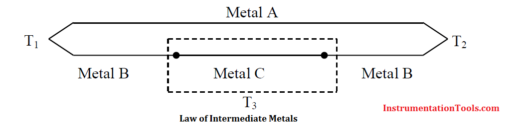
When thermocouples are used, it is usually necessary to introduce additional metals into the circuit This happens when an instrument is used to measure the emf, and when the junction is soldered or welded. It would seem that the introduction of other metals would modify the emf developed by the thermocouple and destroy its calibration. However, the law of intermediate metals states that the introduction of a third metal into the circuit will have no effect upon the emf generated so long as the junctions of the third metal are at the same temperature, as shown in Above Figure

c) Law of intermediate temperatures

The law of intermediate temperatures states that the sum of the emf developed by a thermocouple with its junctions at temperatures T1 and T2, and with its junctions at temperatures T2 and T3, will be the same as the emf developed if the thermocouple junctions are at temperatures T1 and T3.

Law of intermediate temperatures Principle

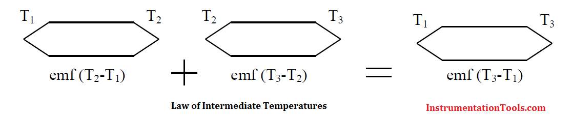
This law, illustrated in above Figure, is useful in practice because it helps in giving a suitable correction in case a reference junction temperature other than 0 °C is employed. For example, if a thermocouple is calibrated for a reference junction temperature of 0 °C and used with a junction temperature of 20 °C, then the correction required for the observation would be the emf produced by the thermocouple between 0 °C and 20 °C.

Also Read: RTD or Thermocouple ?

Don't Miss Our Updates
Be the first to get exclusive content straight to your email.
We promise not to spam you. You can unsubscribe at any time.
Invalid email address
You've successfully subscribed !

Continue Reading

What to Choose RTD or Thermocouple ?
How to Select Right Thermocouple & Thermowell ?
What is RTD Sensitivity ?
What is a Probe Thermometer? How to Calibrate and Use it?
Difficulties with Thermocouples for Temperature Measurement
Thermowell Outer Diameter Larger than Nozzle Inside Diameter?
Share This Article
Facebook Whatsapp Whatsapp LinkedIn Copy Link
Share
Leave a Comment

Leave a Reply Cancel reply

Your email address will not be published. Required fields are marked *

Stay Connected

128.3kFollowersLike
69.1kFollowersFollow
210kSubscribersSubscribe
38kFollowersFollow

Categories

Explore More

What is a Head Mount Temperature Transmitter? – Advantages
Effect of Lead Wire Resistance on RTD
What is a Thermopile ?
Liquid In Glass Thermometer Principle
18 Temperature Sensors Fault Leads to Plant Shutdown
RTD Sensor Connections
What is a Three-wire RTD ?
Disadvantages of Resistance Temperature Detectors

Keep Learning

How Does an Infrared Thermometer Work

How Does an Infrared Thermometer Work?

bimetallic thermometer working principle

Different Types of Thermometers

testing-thermocouples-and-rtds

Testing thermocouples and RTDs using Multi-function Calibrators

Insulation of Thermowell

Facts on Thermowell Insulation Thickness

calibrating-and-testing-rtd-sensors

RTD Calibration Procedure

PTC NTC Thermistors Comparation

Thermistor Working Principle

RTD lead resistances Wiring

Resistance Temperature Detectors Working Principle

Filled-bulb Temperature Measurement

Filled-bulb Temperature Sensors

Learn More

mass spectrometer sample system

Mass Spectrometer Working Principle

Quiz on Alternators, Motors, and Transformers

200+ Quiz on Alternators, Motors, and Transformers

Batteries Connected in Parallel

Battery Operation : Series and Parallel

Crowbar fault protection circuit

Crowbar fault protection circuit

pressure gauge snubber

Pressure Gauge Snubbers

Difference Between CNC Machine and VMC Machine

Difference Between CNC Machine and VMC Machine

Gas-detection-system

Selection Criteria for Toxic Gas Detector

Dynamic Braking Resistor in VFD

Dynamic Braking Resistor in VFD

Menu

  • About
  • Privacy Policy
  • Copyright

Quick Links

  • Learn PLC
  • Helping Hand
  • Part Time Job

YouTube Subscribe

Follow US
All rights reserved. Reproduction in whole or in part without written permission is prohibited.
Welcome Back!

Sign in to your account

Username or Email Address
Password

Lost your password?