Inst ToolsInst ToolsInst Tools
  • Courses
  • Automation
    • PLC
    • Control System
    • Safety System
    • Communication
    • Fire & Gas System
  • Instrumentation
    • Design
    • Pressure
    • Temperature
    • Flow
    • Level
    • Vibration
    • Analyzer
    • Control Valve
    • Switch
    • Calibration
    • Erection & Commissioning
  • Interview
    • Instrumentation
    • Electrical
    • Electronics
    • Practical
  • Q&A
    • Instrumentation
    • Control System
    • Electrical
    • Electronics
    • Analog Electronics
    • Digital Electronics
    • Power Electronics
    • Microprocessor
  • Request
Search
  • Books
  • Software
  • Projects
  • Process
  • Tools
  • Basics
  • Formula
  • Power Plant
  • Root Cause Analysis
  • Electrical Basics
  • Animation
  • Standards
  • 4-20 mA Course
  • Siemens PLC Course
Reading: Zigzag Transformers Theory
Share
Font ResizerAa
Inst ToolsInst Tools
Font ResizerAa
  • Courses
  • Design
  • PLC
  • Interview
  • Control System
Search
  • Courses
  • Automation
    • PLC
    • Control System
    • Safety System
    • Communication
    • Fire & Gas System
  • Instrumentation
    • Design
    • Pressure
    • Temperature
    • Flow
    • Level
    • Vibration
    • Analyzer
    • Control Valve
    • Switch
    • Calibration
    • Erection & Commissioning
  • Interview
    • Instrumentation
    • Electrical
    • Electronics
    • Practical
  • Q&A
    • Instrumentation
    • Control System
    • Electrical
    • Electronics
    • Analog Electronics
    • Digital Electronics
    • Power Electronics
    • Microprocessor
  • Request
Follow US
All rights reserved. Reproduction in whole or in part without written permission is prohibited.
Inst Tools > Blog > Electrical Machines > Zigzag Transformers Theory

Zigzag Transformers Theory

Last updated: June 19, 2018 5:12 pm
Editorial Staff
Electrical Machines
No Comments
Share
4 Min Read
SHARE

The most common connection used in grounding transformers is the Zig-Zag connection. The grounding transformer is commonly referred to by this connection type, the Zigzag Transformer. Grounding Transformers are used for obtaining a grounded neutral on three phase, three-wire systems, providing a return path for zero sequence current generated by the loads in the system or by the fault currents. Sometimes a winding for auxiliary supply can be added besides the zig-zag winding.

Zigzag Transformers Theory

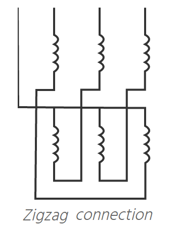
In a case of line-to-ground fault, sufficient current (3I) will flow through the neutral of the transformer, causing opposite current flow (I) in the zig-zag connected windings of the same core leg. This results in no magnetizing effect on the core and provides relatively low impedance from path to ground.

Grounding transformers are most commonly used for short-time operation (approx. up to 30 sec) during the fault currents. However, by connecting reactors they can operate continuously.

The basic parameters required for quoting a grounding transformer are:

Primary Voltage is the system voltage to which the grounded winding is to be connected.

Rated KVA. Because the grounding transformer is normally a short time device, its size and cost are usually lower when compared with a continuous duty transformer of equal kVA rating. For this reason, grounding transformers are often not sized by “kVA” but by their continuous and short time current ratings. Regardless of how you rate it, the grounding transformer must be sized to carry the rated continuous primary phase current without exceeding its temperature limit. Typical continuous current values can be as low as 5 amps to as high as several hundred. Be sure to include any auxiliary loading requirements.

Continuous Neutral Current. The continuous neutral current is defined as three times the phase to current, or in other words, the zero sequence current. This is usually considered to be zero if the system is balanced. However, for the purpose of designing a grounding transformer, it is a value that is expected to flow in the neutral circuit without tripping protective circuits (which would force the current to be zero) or the leakage current to ground that is not a symmetrical function. Again this value is needed to design for thermal capacity of the grounding transformer.

Fault current and duration. This value is needed to calculate the short time heating that results from a fault on the system and should be determined from an engineered system study. Typical values for this range from a few hundred amps to a few thousand amps with duration times expressed in seconds and not cycles. For instance, a value of 400 amps for 10 seconds is typical. The fault duration is a critical parameter for the transformer designer. Where protection schemes use the grounding transformer for tripping functions, a relatively short time duration is specified (5 -30 seconds). On the other hand, a continuous or extended neutral fault current duration would be required when the grounding transformer is used in a ground fault alarm scheme.

Impedance. The impedance can be expressed as a percentage or as an ohm value per phase. In either case it should be chosen so that the un-faulted phase voltages during a ground fault are within the temporary over-voltage capability of the transformer and associated equipment, such as arresters and terminal connectors. This value must come from the system designer.

Secondary connections specify the secondary voltage and connection when applicable.

Don't Miss Our Updates
Be the first to get exclusive content straight to your email.
We promise not to spam you. You can unsubscribe at any time.
Invalid email address
You've successfully subscribed !

Continue Reading

Difference between Permanent Magnet BLDC and DC Motor
Why Starting Current of Induction Motor is High
DC Motor Speed Control
Transformer Tap Changing Working Principle
Transformer Open and Short Circuit Tests
Differences Between AC and DC Motors
Share This Article
Facebook Whatsapp Whatsapp LinkedIn Copy Link
Share
Leave a Comment

Leave a Reply Cancel reply

Your email address will not be published. Required fields are marked *

Stay Connected

128.3kFollowersLike
69.1kFollowersFollow
210kSubscribersSubscribe
38kFollowersFollow

Categories

Explore More

Stepper Motor Basics, Types, Modes, Wiring, Questions
How Motor Star Delta Starter Works ?
6.6kV HV Induction motor Protection
Applications of Synchronous Motors
Advantages and Disadvantages of Squirrel Cage Induction motor
Advantages and Applications of zigzag transformer
What happen When Synchronous Generator loss Excitation
Advantages & Disadvantages of Variable Speed Drives

Keep Learning

BLDC Motor Vs AC Induction Motor

AC Induction Motor Construction

Basics of AC Induction Motors

Transformer Energy Losses & Efficiency

DC Motor Applications in Industries

Squirrel Cage Induction Motor vs Slip Ring Induction Motor

Electrical-Switches-Working-Animation

Difference between Star and Delta Connections

Specific-Conductance-Calibration-Procedure

Types of AC Motors and DC Motors

Induction Motors Faults and Protection

Learn More

Save and BR Memory in Siemens PLC Programming

SAVE and BR Memory Instructions in Siemens PLC Programming

What is a Spare Part

What is a Spare Part? Classification, Cost, Critical Inventory

Create an Application in HMI using Tia Portal

Create an Application in HMI using Tia Portal

quadruple block valve

What is Safety Instrumented Functions ?

Material Certificate versus Positive Material Identification (PMI)

Material Certificate versus Positive Material Identification (PMI)

Function Module in Siemens PLC

What is Function Module in Siemens PLC?

Add On Instructions Programming – Analog Input Devices in Studio 5000

Difference between Current Transformer and Potential Transformer

Difference between Current Transformer and Potential Transformer

Menu

  • About
  • Privacy Policy
  • Copyright

Quick Links

  • Learn PLC
  • Helping Hand
  • Part Time Job

YouTube Subscribe

Follow US
All rights reserved. Reproduction in whole or in part without written permission is prohibited.
Welcome Back!

Sign in to your account

Username or Email Address
Password

Lost your password?