In this post, we will learn the working principle of a single-phase preventer relay.
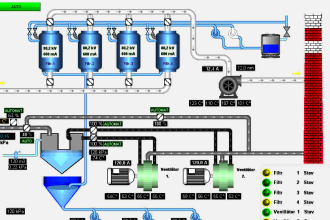
A three-phase supply drives the control components and field devices of an electrical panel. The controlling part is done by PLC.
As the outputs are controlled by PLC, if the three-phase supply fails, then there must be some means to protect the field devices from operating.
Because, if there is any phase failure and still the field device is operating, then it may damage it. If one supply fails, then still the field device like motor will continue to operate.
This will increase the load current in the remaining two phases and result in an unbalanced stator current. This can damage the motor windings.
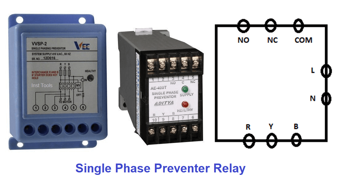
Single Phase Preventer Relay
This protection can be done by a single-phase preventer relay. A single-phase preventer relay is a control device that detects any failure in phase supply and energizes its auxiliary relay contacts.
This contact is then given to the PLC which turns off its outputs through programming written.
Applications
Generally, this relay can be used to protect the circuit against the following types of failures –
- over-voltage,
- under-voltage,
- over frequency,
- under frequency,
- asymmetry,
- phase failure, etc.
Types
This relay works by two methods –
- current sensing and
- voltage sensing.
Both these types continuously monitor the phase sequence and if any failure occurs, then the internal trip circuit activates the relay contacts and sends a trip signal to the PLC.
Working Principle
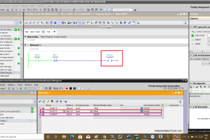
Refer to the image (right-side) above for reference. It generally has 8 terminals. 3 terminals are for 3-phase supply, 2 terminals are for single-phase supply powering the relay device and 3 terminals are for auxiliary contacts.
The device has many settings for timers and other control parameters for accurately monitoring the phase sequence. The circuit inside continuously monitors the unbalance phase sequence or abnormal phase operation, and activates the relay output.
Corresponding logic is written in the PLC to sense the digital input given from this relay and turn off all the outputs. This will disconnect the motor or other field equipment from the three-phase supply and protect it from damage.
Practically, there are many causes that result in phase failure. Sometimes, the contactors of a motor may get open-circuited; or one of the fuses of any three-phase supply gets blown or melts; or the contactors are coated due to oxidation which will cause it to become non-conducting, etc.
In any case, the wrong phase supply can damage the windings of the motor and so, it is necessary to use this device to prevent any untoward incident.
If you liked this article, then please subscribe to our YouTube Channel for Instrumentation, Electrical, PLC, and SCADA video tutorials.
You can also follow us on Facebook and Twitter to receive daily updates.
Read Next: