Why Three Phase Voltage Is 440v?
Contents:
Well, it is not.
I mean, it can be that measuring the voltage between two live phases will result in 440v, but that won’t be a normal case, you probably have a problem in your system.
Momentary heavy loads, wrong transformer taping setting, or switching operations in the power distribution network, may cause short-term deviations out of the tolerance band. Storms and other unusual conditions may cause even larger transient variations.
Some of these deviations can make your three-phase voltages reach 440v, but other than this normally your 3-phase voltage is not 440v.
In a 3-phase system, the voltage between any two phases is greater than a single-phase voltage by a factor of √ 3 or 1.73 roughly. That means if your single-phase voltage is 120v like in the US or Canada, your 3-phase voltage between any two phases will be 208v.
And if you’re single-phase voltage is 220v like in most countries, then you will get 380v between any two phases. The 380v is not a strict value for a three-phase power system as the standards usually allow for a small +/- tolerance to facilitate the interconnectivity and compatibility between different products of different countries and regions.
Most of the world uses a supply voltage of around 6% of 230V. Other places like the United Kingdom and Australia have a voltage supply of 230 V +10%/−6%. This slight difference comes from the fact that most transformers in the United Kingdom are still set to 240V.
The United States and Canada use a supply voltage of 120 volts ± 6%. Other regions like Japan, Saudi Arabia, and some parts of South America use a voltage between 100 V and 127 V.
Historical reasons are the main reason for having different voltage and frequency levels between different regions.
In the US, the start was with the 110 VDC system developed by Edison, and it was chosen 110V as it was thought to be the safe range of voltage value. But with the limitation and challenges facing DC system distribution especially when great distances are involved
AC was introduced. And it made sense to just keep the same voltage so that the same bulbs and AC/DC appliances could also still be used, such as vacuum cleaners, irons, heaters, etc. It did not make sense to change the voltage when so many lights and appliances were already in use. So they kept the value of 110V but switched to an AC system. This value increased over the years to reach the current standard voltage value of 120V.
Japan for some reason has 100 volts voltage supply, half of the country is at 50Hz, the other at 60Hz. This is probably the result of German versus US equipment back in the 1890s.
In Europe, the 120 V system was also used, just like in Japan and the US today, but it was deemed necessary to increase the voltage to get more power transferred with fewer losses and to reduce the cost of conductors used. So, in 1899, the Berliner Elektrizitäts-Werke (BEW), a Berlin electrical utility, introduced a new 220V system to take advantage of all the benefits associated with a higher voltage level compared to a 110V system.
The company was able to offset the cost of converting the customer’s equipment from 110v to 220v by the resulting saving in distribution conductors cost.
This became the model for electrical distribution in Germany and later the rest of Europe.
The main reason for that is the hustle and troubles that manufacturers and power utilities will face to change their already established systems and products to the new unified standards.
Changing the voltage system from 110 to 230 or the opposite or from 50 Hz system to 60 Hz system will force the change of all involved systems from generation to distribution.
This is a huge cost to be paid. It was very costly back then in the 1880s when electricity was just used for home lighting and simple electrical devices. Imagine now when electricity is a crucial part of any aspect of our lives. That is why a global voltage standard is unlikely to happen. However, attempts to standardize systems that use the same voltage levels were made.
International Standard IEC 60038, defines a set of standard voltages for use in low-voltage and high-voltage AC and DC electricity supply systems.
Check the following table.
| Year | Neutral-Phase [V] / Phase-Phase [V] | Tolerance |
| — 1987 | 220 V / 380 V | – 10% .. +10% |
| 1988 — 2003 | 230 V / 400 V | – 10% .. + 6% |
| 2003 — | 230 V / 400 V | – 10% .. +10% |
The advantages of using 3-phase systems over single phase are clear, as they provide more power transmission, and also the reduction in transferred current will reduce the cost of used conductors.
Power transferred in 3 phase system is almost twice the power of a single phase (roughly 1.732 times the power of a single phase); it’s not three times the power, as one might think, because of the 120° electrically between each two-phase. See picture 1.
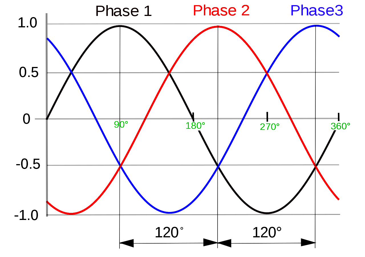
This is true because the generator (alternator) is mechanically constructed such that each winding is mechanically placed around the stator ring 120° apart.
Some would argue that a system with more phases will present more benefits compared to a 3-phase system, as a 3-phase system has done compared to a single-phase system, but as we mentioned before changing the currently known, used, and approved system will result in a lot of costs for changing the already existing systems.
Plus, the designing and manufacturing of motors and generators with more than 3 phases will be extremely complicated and costly. That is why the 3 phase system was approved to be the standard one.
But, it’s worth mentioning that for some special applications, special generators and motors with more phases than 3 are used.
Read Next:
This article is about controlling the Pneumatic cylinder and Pneumatic motor in the assembly line…
In this post, we will learn the basic requirements for a network switch to be…
The PLC panel and MCC panel interface signals are start, stop, run feedback, trip, local…
In this article, we are going to discuss about shutter door control using induction motor…
Electrical Drives control the motion of electric motors. Motion control is required in industrial and…
PLC ladder logic design to control 3 motors with toggle switch and explain the program…

View Comments
440 V? Please check it. The phase-phase voltage is 400V.
Vp-p=V.single.phase*3^1/2
This article is wrong please modify it correctly.
It's correct
No it is NOT correct.
You do not take the phase to phase voltage as double the phase to neutral voltage.
I did the mathematical analysis many years ago when I was at university.
The voltage of the two phase conductors are not going up and down together with a phase difference of zero degrees.
Also the voltages are not 180 degrees out of phase with each other, and this is the only way you could obtain a phase to phase voltage which is double the phase to neutral voltage.
The voltage wave forms in a 3 phase system have 120 degrees phase difference. There are only two ways to calculate the phase to phase voltage, the first is to use trigonometry, sin() function, or use complex numbers to represent each sinusoidal waveforms and do conversions from polar form to argand form and back again.
220 volts phase voltage is 380 volts phase to phase.
ALL posters on this website saying anything different are wrong.
NO IT IT ABSOLUTELY NOT CORRECT.
Check any reputable source!
Also the fuse/disconnect is incorrectly illustrated on the neutral - neutrals NEVER get fused, or disconnected, IN ANY COUNTRY!!! [AFAIK]
It's incorrect, the voltage is 400V
No it is not 400 volts.
The phase voltage required to achieve a phase to phase voltage of 400 volts is 230 volts.
this article need some modification
the relation between the voltage of (phase to phase)=sqrt(3) phase to neutral
we don't multiply by two
BR
It’s not just multiplied by 2, it’s taking 220 times root 3 then dividing it by the sin of 120(phase to phase angle in 3 phase) so 220x1.732/0.866=440
This is so wrong: you are mixing up peak voltage and rms voltage in your calculation.
All the other guys who protest are correct in a 3ph system where neutral to 1ph is 220, the 3ph voltage (from one ph to another) is approx 380V.
Or 230/400,
or 254/440
or 277/440.
The factor is sq.root of 3. It is pure trigonometry.
Just don't mix up peak voltage and rms voltage.
Can you fix Experienced DIY's typo?
Those are excellent references he/she provided (except);
'277/440' should be '277/480'
These references mean:
'phase-to-neutral voltage'/'phase-to-phase voltage'.
There is also 120V/208V, a common USA configuration.
Also, Wikipedia has a 'Mains electricity by country' chart...
Experienced DIY is correct, (you are using the wrong math), it is root 3 times phase to neutral.
I don't think that figure you used is for RMS either; I think you are double converting...
I would have to check if root 3 IS the sin 120º... [nope, not that either]
Think you mixed in a figure for dog-leg third phase to CT neutral! [hi-leg to grounded conductor]
AHA is correct
This article needs to be fixed.
Examples of 3 Phase converted to single Phase Live/N:
440V 3 Phase = 440/sqrt(3) = 254V
415V 3 Phase = 415/sqrt(3) = 240V
380V 3 Phase = 380/sqrt(3) = 220V
200V 3 Phase = 200/sqrt(3) = 115V
If you don't believe this check the supplies in your own country
Please fix this website.
"the voltage across the 3 phase is 440V because we check the voltage between any two-phase RY or YB or BR"
Just consider any phase to phase visually and you can see that the voltage cannot be 440VAC.
120 degree difference in phase relationship negates the possibility.
For a 440VAC solution, two sines would have to be perfectly in phase.
220V Line to Neutral is 380V Line-Line for 3-phase power. Curtis Gomez is correct. The three phases are120 degrees apart, not 180 degrees apart. Please fix this article.
The article is riddled with errors and should be completely rewritten. The author clearly has no proper understanding of AC theory and three phase systems in particular.
You should be totally embarrassed sharing this.