Control valves used in pneumatic and hydraulic fluid power systems often take the form of a spool mechanism, and the fluid power schematic symbols for these spool valves are quite unlike that of valve symbols in P&IDs and loop diagrams:
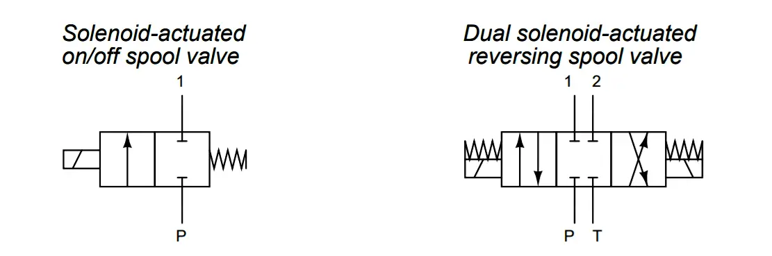
Explain what these spool valve symbols represent, and how they are to be interpreted. Also, comment on the construction of a spool valve.
Answer:
The symbols show each valve’s “normal” (unactuated) position. To understand what happens when the valve is actuated, you must visualize the boxes sliding over into alignment with the inlet/outlet pipes, like this:
The same holds for the reversing valve, except that it has three positions:
Share your answers with us through the below comments section.
Read Next:
Credits: Tony R. Kuphaldt
The PLC panel and MCC panel interface signals are start, stop, run feedback, trip, local…
In this article, we are going to discuss about shutter door control using induction motor…
Electrical Drives control the motion of electric motors. Motion control is required in industrial and…
PLC ladder logic design to control 3 motors with toggle switch and explain the program…
VFD simulator download: Master the online tool from the Yaskawa V1000 & programming software for…
The conveyor sorting machine is widely used in the packing industries using the PLC program…


