Inst ToolsInst ToolsInst Tools
  • Courses
  • Automation
    • PLC
    • Control System
    • Safety System
    • Communication
    • Fire & Gas System
  • Instrumentation
    • Design
    • Pressure
    • Temperature
    • Flow
    • Level
    • Vibration
    • Analyzer
    • Control Valve
    • Switch
    • Calibration
    • Erection & Commissioning
  • Interview
    • Instrumentation
    • Electrical
    • Electronics
    • Practical
  • Q&A
    • Instrumentation
    • Control System
    • Electrical
    • Electronics
    • Analog Electronics
    • Digital Electronics
    • Power Electronics
    • Microprocessor
  • Request
Search
  • Books
  • Software
  • Projects
  • Process
  • Tools
  • Basics
  • Formula
  • Power Plant
  • Root Cause Analysis
  • Electrical Basics
  • Animation
  • Standards
  • 4-20 mA Course
  • Siemens PLC Course
Reading: What is the thermal effect on Sensors?
Share
Font ResizerAa
Inst ToolsInst Tools
Font ResizerAa
  • Courses
  • Design
  • PLC
  • Interview
  • Control System
Search
  • Courses
  • Automation
    • PLC
    • Control System
    • Safety System
    • Communication
    • Fire & Gas System
  • Instrumentation
    • Design
    • Pressure
    • Temperature
    • Flow
    • Level
    • Vibration
    • Analyzer
    • Control Valve
    • Switch
    • Calibration
    • Erection & Commissioning
  • Interview
    • Instrumentation
    • Electrical
    • Electronics
    • Practical
  • Q&A
    • Instrumentation
    • Control System
    • Electrical
    • Electronics
    • Analog Electronics
    • Digital Electronics
    • Power Electronics
    • Microprocessor
  • Request
Follow US
All rights reserved. Reproduction in whole or in part without written permission is prohibited.
Inst Tools > Blog > Instrumentation Design > What is the thermal effect on Sensors?

What is the thermal effect on Sensors?

Last updated: October 4, 2017 9:04 am
Editorial Staff
Instrumentation Design
No Comments
Share
4 Min Read
SHARE

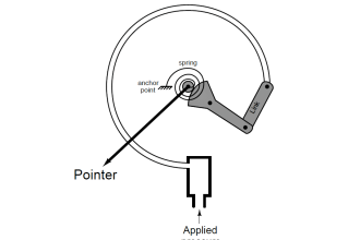
Thermal effect on sensor/transmitter can be found mainly on Zero or Span effects.

What is the thermal effect on zero?

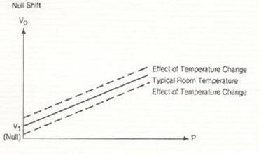
Thermal zero shift represents the change in null resulting from a change in temperature. Null shift is not a predictable error because it can move up and down from unit to unit.

Changes in temperature will cause the entire output curve to move up or down along the output axis.

What is the thermal effect on zero

The zero shifts due to temperature could be caused by the difference in the thermal coefficient of expansion of the sensor parts.

To minimise the zero error with temperature, the differential expansion of the mechanical components must nearly balance out. And to achieve this the sensor must be temperature compensated over a stated range.

One of the methods used for temperature compensation involves the addition of a temperature-sensitive resistor on one arm of the bridge. The value of the resistor is determined from a temperature test run in which the change in zero reading for the given temperature is found.

Watch out

Different manufacturers specify thermal zero shift in different ways: as error per degree Celsius, such as ±0.01%FS/°C; as a total temperature effect, in the form of ±1% of FS; or as an error band, such as ±1% over a 50°C temperature range. There are many more; some with reference to full scale, others to reading. But in each case the specified error is only valid over the compensated temperature range.

Note that the temperature effect is only valid when the complete sensor housing is heated up. This is because some sensors have their temperature compensation at the rear of the housing.

A few manufacturers include both zero and span as a total value.

What is the thermal effect on span?

Span or sensitivity temperature shift represents the change in sensitivity due to changes in temperature. A change in temperature will cause a change in the slope of the sensor output curve.

The span shift due to temperature could typically be caused by the change in elasticity or spring constant of the gauges used in a sensor.

To minimize the span error with temperature, the most common used method for temperature compensation involves the addition of a temperature-sensitive resistor in series with the bridge work. The value of the resistor is determined from a temperature test run in which the change in span reading for the given temperature is found.

Normally the specified error is percentage of reading per degree Celsius including all error effects on linearity, hysteresis, repeatability and gradient sensitivity.

Watch out

Different manufacturers specify thermal effect on span in different ways: as error per degree Celsius, such as ±0.01%FS/°C; as a total temperature effect, in the form of ±1% of FS; or as an error band, such as ±1% over a 50°C temperature range. There are many more; some with reference to full scale, others that refer to reading. But in each case the specified error is only valid over the compensated temperature range.

Note that the temperature effect is only valid when the complete sensor housing is heated up. This is because some sensors have their temperature compensation at the rear of the housing.

A few manufacturers include both zero and span as a total value.

Don't Miss Our Updates
Be the first to get exclusive content straight to your email.
We promise not to spam you. You can unsubscribe at any time.
Invalid email address
You've successfully subscribed !

Continue Reading

How to Select an Actuator for Valve
Instrumentation and Electrical Teams Interactions (Detail Design Engineering)
Pressure Control Valves vs Pressure Regulators
Process Design of Instrument Air System
How to select a load cell?
Cable Screen shall not be Grounded at Field Device ?
Share This Article
Facebook Whatsapp Whatsapp LinkedIn Copy Link
Share
Leave a Comment

Leave a Reply Cancel reply

Your email address will not be published. Required fields are marked *

Stay Connected

128.3kFollowersLike
69.1kFollowersFollow
210kSubscribersSubscribe
38kFollowersFollow

Categories

Explore More

How to Select the Right Panel Enclosure for Your Application?
Blast Furnace Panel Modification to Reduce Down Time by 60 to 70%
Important Factors Consider during Piping Design
Safety Instrumented System Module Failure
Heat Tracing Problems
Why we use Cable Shielding with Ferrites ?
Switch or Transmitter
5 Most Common Mistakes When Specifying Valves

Keep Learning

Guided Wave Radar Level Transmitter Compensation

Guided Wave Radar Level Sensor Pressure and Temperature Effects

Panel Ground Noise

Floating Vs. Grounded Voltage

Instrumentation and Control Project Packages

Instrumentation and Control Project Packages – Detail Engineering

Instrument Heat Trace

Electrical Heat Tracing

Earth Meter Working Principle

How Earth Resistance is Measured

Level Transmitter Design

Level Transmitter and Level Gauge Design Tips

Instrument Process Datasheet

Why is an Instrument Process Datasheet Required?

LCS Configuration equipped with LOTO Facility

Motor Control Signal Interface

Learn More

Magnetic Flow Meters

Magnetic Flow Meters Installation Guidelines

Digital Electronics Multiple Choice Questions

4-Bit Parallel Adder and Subtractor Objective Questions

Comparison of Accuracy and Precision

Difference between Accuracy and Precision

pH Analyzers Interview Questions Answers

pH Analyzer Interview Questions and Answers

Basic Configuration of Motor Operated Valve

Rotork Motor Operated Valve Basic Configuration

PLC Ladder Logic Simulator Mobile Apps For Android

PLC Ladder Logic Simulator Mobile Apps For Android

steadily pour a liquid into vertical tube

Vertical Tube Liquid Level Equilibrium

Locked Open (LO) and Locked Close (LC) Valves

Locked Open (LO) and Locked Closed (LC) Valves

Menu

  • About
  • Privacy Policy
  • Copyright

Quick Links

  • Learn PLC
  • Helping Hand
  • Part Time Job

YouTube Subscribe

Follow US
All rights reserved. Reproduction in whole or in part without written permission is prohibited.
Welcome Back!

Sign in to your account

Username or Email Address
Password

Lost your password?