When a venturi flow meter is placed in a pipe carrying the fluid whose flow rate is to be measured, a pressure drop occurs between the entrance and throat of the venturi meter.
This pressure drop is measured using a differential pressure sensor and when calibrated this pressure drop becomes a measure of flow rate.
The below animations shows the working of venturi flow meter.
The following are the main parts and areas of the venturi meter:
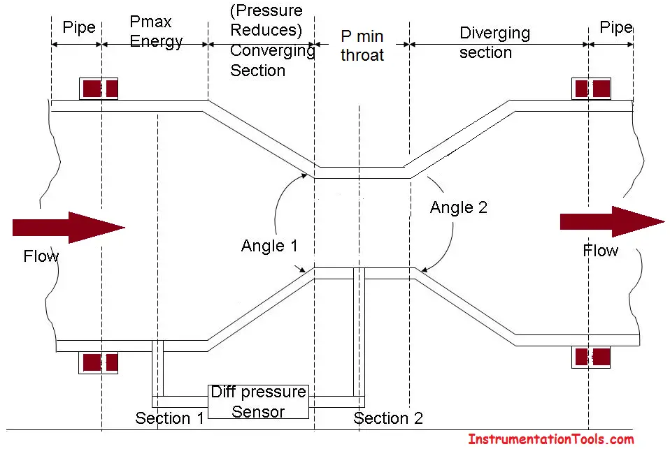
The entry of the venture is cylindrical in shape to match the size of the pipe through which fluid flows. This enables the venture to be fitted to the pipe.
After the entry, there is a converging conical section with an included angle of 19’ to 23’.
Following the converging section, there is a cylindrical section with a minimum area called as the throat.
After the throat, there is a diverging conical section with an included angle of 5’ to 15’.
Openings are provided at the entry and throat (at sections 1 and 2 in the diagram) of the venture meter for attaching a differential pressure sensor (u-tube manometer, differential pressure gauge, etc) as shown in the diagram.
The fluid whose flow rate is to be measured enters the entry section of the venturi meter with a pressure P1.
As the fluid from the entry section of venturi meter flows into the converging section, its pressure keeps on reducing and attains a minimum value P2 when it enters the throat. That is, in the throat, the fluid pressure P2 will be minimal.
The differential pressure sensor attached between the entry and throat section of the venturi meter records the pressure difference(P1-P2) which becomes an indication of the flow rate of the fluid through the pipe when calibrated.
The diverging section has been provided to enable the fluid to regain its pressure and hence its kinetic energy. The lower the angle of the diverging section, the greater the recovery.
If you liked this article, then please subscribe to our YouTube Channel for Instrumentation, Electrical, PLC, and SCADA video tutorials.
You can also follow us on Facebook and Twitter to receive daily updates.
Read Next:
In this article, we are going to discuss about shutter door control using induction motor…
Electrical Drives control the motion of electric motors. Motion control is required in industrial and…
PLC ladder logic design to control 3 motors with toggle switch and explain the program…
VFD simulator download: Master the online tool from the Yaskawa V1000 & programming software for…
The conveyor sorting machine is widely used in the packing industries using the PLC program…
Learn the example of flip-flop PLC program for lamps application using the ladder logic to…


View Comments
Its educative.
Thanks,
From Emgr G.C. Achakpo