Time Response of First Order Systems Objective Questions
1. First order system is defined as :
a) Number of poles at origin
b) Order of the differential equation
c) Total number of poles of equation
d) Total number of poles and order of equation
Answer: d
Explanation: First order system is defined by total number of poles and also which is same as the order of differential equation.
2. A unit step is applied at t=0 to a first order system without time delay. The response has the value of 1.264 units at t=10 mins, and 2 units at steady state. The transfer function of the system is_____________
a) 3/(1+600s)
b) 2/(1+500s)
c) 5/(1+220s)
d) 2/(1+600s)
Answer: d
Explanation: a(t)= k[1-e^-t/T] K=2
0.632= 1-e^-10/T
T=600 sec
G(s)=2/(1+600s).
3. The transfer function of the system is G(s) =100/(s+1) (s+100). For a unit step input to the system the approximate settling time for 2% criterion is:
a) 100 sec
b) 4 sec
c) 1 sec
d) 0.01 sec
Answer: b
Explanation: G(s) =100/(s+1) (s+100)
Taking the dominant pole consideration,
S=-100 pole is not taken.
G(s)= 100/s+1
Now it is first order system, ts=4T=4 sec.
4. If a first order system and its time response to a unit step are as shown below, the gain K is :
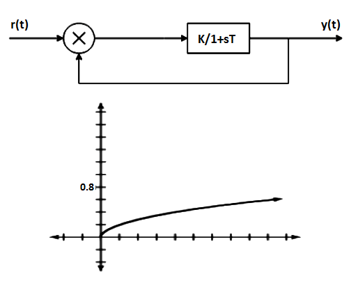
a) 0.25
b) 0.8
c) 1
d) 4
Answer: d
Explanation: Y(s)/R(s)=K/1+sT+K
By, use of partial fraction, K/T/s+(K+1/T)
Taking inverse Laplace transform on both the sides
Y(t)=K/K+1[1-e^(K+1/T)t] K=4
5. The unit impulse response of a system having transfer function K/(s+a) is shown below. The value of a is :
a) t1
b) t2
c) 1/t1
d) 1/t2
Answer: d
Explanation: G(s) = K/s+a
C(s) =K/(s+a) Since R(s) =1
C(t) =Ke^-at
T=1/a
C(t) =0.37K
T= t2=1/a.
6. A system with transfer function 1/Ts+1, subjected to a step input takes to seconds to reach 50% of step height. The value of t is :
a) 6.9s
b) 10s
c) 14.4s
d) 20s
Answer: c
Explanation: The response of a first order system is:
A(t)=a[1-e^-t/T] ½= 1-e^-10/t
T= 14.43 sec.
7.A first order system and its response to a unit step input are shown in figure below. The system parameters are____________
a) a=5 and k=12
b) a=10 and k=5
c) a=5 and k=10
d) a=8 and k=9
Answer: c
Explanation: time constant=0.2 sec.
1/a=0.2
a=5
final value=lims→0 sC(s) =K/a
K/a=2
K=10.
8. Assertion (A): It is observed that step function is first derivative of a ramp function and impulse function is first derivative of a step function.
Reason (R): From the derived time response expression it is concluded that the output time response also follows the same sequence as that of input functions.
a) Both A and R are true and R is the correct explanation of A
b) Both A and R are true but R is not correct explanation of A
c) Both A is True but R is false
d) Both A is False but R is true
Answer: b
Explanation: If response due to one standard signal is known then response due to other signals can also be derived.
9. Laplace transform of unit impulse signal is :
a) A/s
b) A
c) 1
d) 1/s
Answer: c
Explanation: Laplace response of impulse signal is one which implies Laplace response is systems response.
10. Time response during steady state the output velocity matches with the input velocity but lags behind the input by T.
a) True
b) False
Answer: a
Explanation: In first order systems the time response during steady state the output velocity matches.
In this post, we will learn the basic requirements for a network switch to be…
The PLC panel and MCC panel interface signals are start, stop, run feedback, trip, local…
In this article, we are going to discuss about shutter door control using induction motor…
Electrical Drives control the motion of electric motors. Motion control is required in industrial and…
PLC ladder logic design to control 3 motors with toggle switch and explain the program…
VFD simulator download: Master the online tool from the Yaskawa V1000 & programming software for…

