Inst ToolsInst ToolsInst Tools
  • Courses
  • Automation
    • PLC
    • Control System
    • Safety System
    • Communication
    • Fire & Gas System
  • Instrumentation
    • Design
    • Pressure
    • Temperature
    • Flow
    • Level
    • Vibration
    • Analyzer
    • Control Valve
    • Switch
    • Calibration
    • Erection & Commissioning
  • Interview
    • Instrumentation
    • Electrical
    • Electronics
    • Practical
  • Q&A
    • Instrumentation
    • Control System
    • Electrical
    • Electronics
    • Analog Electronics
    • Digital Electronics
    • Power Electronics
    • Microprocessor
  • Request
Search
  • Books
  • Software
  • Projects
  • Process
  • Tools
  • Basics
  • Formula
  • Power Plant
  • Root Cause Analysis
  • Electrical Basics
  • Animation
  • Standards
  • 4-20 mA Course
  • Siemens PLC Course
Reading: Facts on Thermowell Insulation Thickness
Share
Font ResizerAa
Inst ToolsInst Tools
Font ResizerAa
  • Courses
  • Design
  • PLC
  • Interview
  • Control System
Search
  • Courses
  • Automation
    • PLC
    • Control System
    • Safety System
    • Communication
    • Fire & Gas System
  • Instrumentation
    • Design
    • Pressure
    • Temperature
    • Flow
    • Level
    • Vibration
    • Analyzer
    • Control Valve
    • Switch
    • Calibration
    • Erection & Commissioning
  • Interview
    • Instrumentation
    • Electrical
    • Electronics
    • Practical
  • Q&A
    • Instrumentation
    • Control System
    • Electrical
    • Electronics
    • Analog Electronics
    • Digital Electronics
    • Power Electronics
    • Microprocessor
  • Request
Follow US
All rights reserved. Reproduction in whole or in part without written permission is prohibited.
Inst Tools > Blog > Instrumentation Design > Facts on Thermowell Insulation Thickness

Facts on Thermowell Insulation Thickness

Last updated: September 22, 2019 7:56 pm
Editorial Staff
Instrumentation Design Temperature Measurement
2 Comments
Share
3 Min Read
SHARE

Can Insulation Thickness affect Thermowell U-Length ?

Thermowell Tip must be at least 2 mm immersed in Liquid whose temperature is to be measured (As per API 551)

Contents
Can Insulation Thickness affect Thermowell U-Length ?Thermowell Insulation ThicknessGood Engineering practiceNot so good engineering practice !!

In 2-phase service also it is recommended that Tip must be all the way up to Liquid phase for better measurement (PIP Std :-Temperature Measurement criteria)

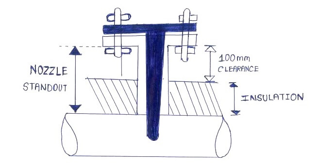
A Standout of 6” is usually taken as rule of thumb and according the U-length calculated so that Thermowell tip is inserted at least 2 mm in process or more.(depending on client standards)

Now consider The Design Temperature got updated at the latter stages . At this point due to change in Temperature the Insulation thickness increased.

Does this change in insulation affect the Thermowell U-Length?

Yes it does!!

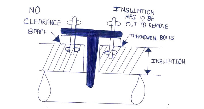
Good Engineering practice is that there has to be clearance of 100 mm (4 inches) between Insulation and the nozzle .This is followed in standard cases because whenever we need to remove the Thermowell and if insulation is all the way up to the nozzle then we will have to cut the insulation to get to the Bolts, Which is not a good practice.

Thermowell Insulation Thickness

Refer the diagram Below .

Good Engineering practice

Thermowell Insulation Thickness

Not so good engineering practice !!

Insulation of Thermowell

Hence for Insulation between 0 to 50 mm we could have Standard standout of 150 mm ( 6 Inch)

But when insulation is 100 mm then standout must increase to 200 mm (8 inches)

Clearance (100 mm) = Standout (200 mm) – Insulation Thickness (100 mm)

Similarly if insulation is 150 mm then standout must increase to 250 mm (10 inches) so on and so forth.

So the Relation is as follows

Insulation (On pipe)>>affects>>Standout (Nozzle)>>affects>>U-length (Thermowell)

Hence we must cross verify at later stages before purchase that will standout affected due to insulation !!

Accordingly ensure whether the thermowell tip actually is in contact with process as per our requirement !!

Thanks for reading !!

Hope this is helpful

PS : As always this is as per best of my current understanding !! I would be very grateful if any updates or corrections are required.

Author : Asad Shaikh

Profile : Linkedin

Articles You May Like :

RTD Troubleshooting Tips

What is Temperature Switch

Temperature Interview Questions
Bi-metal Temperature Sensors

Types of Thermometers

Don't Miss Our Updates
Be the first to get exclusive content straight to your email.
We promise not to spam you. You can unsubscribe at any time.
Invalid email address
You've successfully subscribed !

Continue Reading

Vendor View of Supplying Industrial Process Control & Safety Systems
Temperature Transmitter Preventive Maintenance
All About Turbine Meters
Temperature Sensors Interview Questions
Thermowell Design Guidelines
Instrumentation and Control (I&C) Design
Share This Article
Facebook Whatsapp Whatsapp LinkedIn Copy Link
Share
2 Comments
  • Varneek Mathur says:
    October 29, 2019 at 8:07 pm

    Hi..
    Well written the full article. However i have one observation.
    “Thermowell Tip must be at least 2 mm immersed in Liquid whose temperature is to be measured (As per API 551)”
    But thermowell tip shall be min 2 inches (instead of 2 mm) immersed in the liquid.
    So we can rewrite as:
    “Thermowell Tip must be at least 2 inches immersed in Liquid whose temperature is to be measured (As per API 551)”

    Reply
    • Marcos Escobar says:
      October 11, 2021 at 6:31 pm

      You are correct, it is 2″. Also wondering why the free space from top of insulation to bottom? of the flange is recommended 4″ when I think 2″ will be sufficient (any thoughts?)

      Reply

Leave a Reply Cancel reply

Your email address will not be published. Required fields are marked *

Stay Connected

128.3kFollowersLike
69.1kFollowersFollow
210kSubscribersSubscribe
38kFollowersFollow

Categories

Explore More

How to Select a pH or ORP Meter
Types of Thermowells
Important Factors Consider during Piping Design
Load Cell Design
Temperature Switch Working Principle
Thermocouple Working Principle
Electrical Signal and Control Wiring
Transmitter Minimum Span, Accuracy & Turndown

Keep Learning

Where should we terminate the shield and why

Where should we Terminate the Cable Shields ?

How to Select a Flow Meter

How to Select a Flow Meter

RTD installed after the Orifice Plate

Why RTD installed after the Orifice Plate ?

Convert 2 wire RTD to 4 wire RTD Sensor

How to Convert 2 wire RTD into 3 or 4 wire RTD?

What is Temperature

What is Temperature ?

Pressure Sensor Specifications

Pressure Sensor Specifications

Formula of 2 Wire RTD, 3 Wire RTD & 4 Wire RTD

Formula of 2 Wire RTD, 3 Wire RTD & 4 Wire RTD

Thermowell Outer Diameter larger than Nozzle Inside Diameter

Thermowell Outer Diameter Larger than Nozzle Inside Diameter?

Learn More

Fieldbus and Profibus

Difference between Fieldbus and Profibus

Leave Operational Logic in the PLC

#3 PLC Best Practices – Leave Operational Logic in the PLC wherever feasible

Procedure for the Repair of Control Valve

Basic Steps and Procedure for the Repair of Control Valve

SCADA System

What is SCADA System?

Power Electronics Objective Questions

Choppers Quiz

Free Download Industrial Control System Book

Free Download Industrial Control System Book

PID Controller Functionality

PID Controller Theory

Siemens TIA Portal Free Version Download

Siemens TIA Portal Free Version Download

Menu

  • About
  • Privacy Policy
  • Copyright

Quick Links

  • Learn PLC
  • Helping Hand
  • Part Time Job

YouTube Subscribe

Follow US
All rights reserved. Reproduction in whole or in part without written permission is prohibited.
Welcome Back!

Sign in to your account

Username or Email Address
Password

Lost your password?