Categories: Power Electronics

How to Test TRIAC with Multimeter

How to test TRIAC with Digital Multimeter OR using Ohmmeter?

In this short post we will discuss about how to test the Triac.

triac

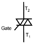
Introduction about Triac:

  1. TRIAC = TRIode for Alternating Current.
  2. The TRIAC is 5 layer, 3 terminal Power semiconductor device.
  3. It has a pair of phase controlled SCRs connected in inverse parallel manner on the same chip.
  4. It is a bidirectional device, means it can conduct current in both the directions.


Step by step Procedure to test the triac:

  1. Keep the digital multimeter into Ohmmeter mode.
  2. Using a junction diode determine which ohmmeter lead is positive and which is negative. The ohmmeter will indicate continuity only when the positive lead is connected to the anode and the negative lead is connected to the cathode.
  3. Connect the positive lead of Ohmmeter to MT2 and the negative lead to MT1. The ohmmeter should indicate no continuity through the triac.
  4. Using a jumper lead connect the Gate of the Triac to MT2. The multimeter should indicate a forward diode junction.
  5. Reconnect the Triac so that MT1 is connected to the positive lead of ohmmeter and MT2 is connected to the negative lead. The multimeter should indicate no continuity through a Triac.
  6. Using a jumper lead, again connect the gate to MT2. The ohmmeter should indicate a forward diode junction.
You've successfully subscribed !

View Comments

  • I am currently testing a triac, I'm getting readings in megaohms across M1 and M2 , is that close enough to no reading or open?

    • I am getting readings around 50 ohm with floating gate pin. Mine obviously is damaged.
      You should test it with the diode option not the ohms.

      • hai andres.. What is the actual reading (ohm) for the triac after test. If still inbgood condition. Tq

  • I observed that one of the pins should conduct with the tab. If none conducts, you have a broken triac.

Share

Recent Articles

  • PLC Tutorials

Shutter Door Control using Motor and Limit Switches

 In this article, we are going to discuss about shutter door control using induction motor…

6 days ago
  • Electrical Basics

Electrical Drives – Modes, Types, Speed Control Applications

Electrical Drives control the motion of electric motors. Motion control is required in industrial and…

6 days ago
  • PLC Tutorials

PLC Ladder Logic Design: Control 3 Motors with Toggle Switch

PLC ladder logic design to control 3 motors with toggle switch and explain the program…

3 weeks ago
  • PLC Tutorials

VFD Simulator Download – Free Yaskawa V1000 Software

VFD simulator download: Master the online tool from the Yaskawa V1000 & programming software for…

6 days ago
  • PLC Tutorials

Conveyor Sorting Machine PLC Program with Calculation Function

The conveyor sorting machine is widely used in the packing industries using the PLC program…

1 week ago
  • PLC Tutorials

Example of Flip-Flop PLC Program for Lamps Application

Learn the example of flip-flop PLC program for lamps application using the ladder logic to…

1 week ago