Inst ToolsInst ToolsInst Tools
  • Courses
  • Automation
    • PLC
    • Control System
    • Safety System
    • Communication
    • Fire & Gas System
  • Instrumentation
    • Design
    • Pressure
    • Temperature
    • Flow
    • Level
    • Vibration
    • Analyzer
    • Control Valve
    • Switch
    • Calibration
    • Erection & Commissioning
  • Interview
    • Instrumentation
    • Electrical
    • Electronics
    • Practical
  • Q&A
    • Instrumentation
    • Control System
    • Electrical
    • Electronics
    • Analog Electronics
    • Digital Electronics
    • Power Electronics
    • Microprocessor
  • Request
Search
  • Books
  • Software
  • Projects
  • Process
  • Tools
  • Basics
  • Formula
  • Power Plant
  • Root Cause Analysis
  • Electrical Basics
  • Animation
  • Standards
  • 4-20 mA Course
  • Siemens PLC Course
Reading: Temperature Calibration Bath Principle
Share
Font ResizerAa
Inst ToolsInst Tools
Font ResizerAa
  • Courses
  • Design
  • PLC
  • Interview
  • Control System
Search
  • Courses
  • Automation
    • PLC
    • Control System
    • Safety System
    • Communication
    • Fire & Gas System
  • Instrumentation
    • Design
    • Pressure
    • Temperature
    • Flow
    • Level
    • Vibration
    • Analyzer
    • Control Valve
    • Switch
    • Calibration
    • Erection & Commissioning
  • Interview
    • Instrumentation
    • Electrical
    • Electronics
    • Practical
  • Q&A
    • Instrumentation
    • Control System
    • Electrical
    • Electronics
    • Analog Electronics
    • Digital Electronics
    • Power Electronics
    • Microprocessor
  • Request
Follow US
All rights reserved. Reproduction in whole or in part without written permission is prohibited.
Inst Tools > Blog > Temperature Measurement > Temperature Calibration Bath Principle

Temperature Calibration Bath Principle

Last updated: November 4, 2018 10:59 pm
Editorial Staff
Temperature Measurement
2 Comments
Share
3 Min Read
SHARE

A temperature calibration bath provides precise temperatures for more calibration of RTD, Thermocouples, PRTs, SPRTs, and liquid in glass (LIG) thermometers.

The principle of a dry block temperature calibrator bath is basically very simple:

Heating up a metal block and keeping the temperature stable.

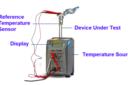
Temperature calibration bath used for themocouple/RTD testing & calibration purpose. Basically the calibration bath contains some type of heating elements which are used to raise the bath temperature. For Maintaining the Temperature, we need a internal temperature sensor like RTD, so we can control the bath temperature with a simple inbuilt PID controller. The setpoints of the calibration bath will be given by the operator/user using front end knobs. The Device under test i.e. Temperature sensor which is to be calibrated will be placed inside the temperature bath. The bath maintains the temperature as per the user settings or requirements.

If we place RTD inside the temperature calibration bath, then maintain fixed temperature say 100 Deg C and note down the Resistance value of RTD. Again increase the temperature say 120 Deg C and note down the resistance value of RTD and repeat the same for three more different temperatures. Also we will check from increasing to decreasing order. Finally cross check the noted resistance values with standard Resistance Vs Temperature chart and note down the differences of actual and standard readings to find out the drift or error values.

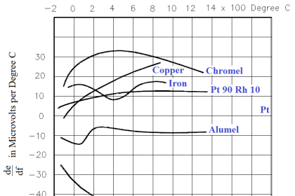
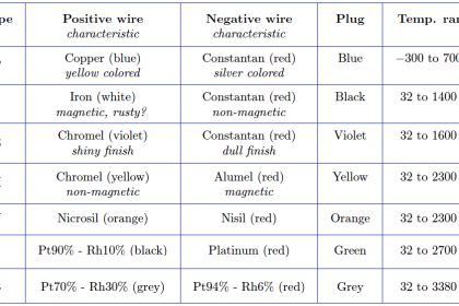
The procedure will be same for thermocouple also, but here we measure mV and check with Temperature Vs mV chart for that specific thermocouple type. Note : Thermocouple chart will be different for each type of thermocouple.

This basic design gives the user a lot of advantages compared to the more traditional liquid baths.

– Heating up and cooling down much faster
– Much wider temperature ranges
– Physically smaller and lighter
– Designed for industrial applications
– Models with completely integrated calibration solutions

Picture:

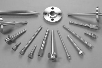
1. Sensor-under-test
2. Solid metal block (dry block)
3. Interchangeable inserts for the sensor-under-test
4. Internal RTD reference sensor
5. Heating elements
6. Cooling fan

Temperature Calibration Bath

Image courtesy  :Ametek

Don't Miss Our Updates
Be the first to get exclusive content straight to your email.
We promise not to spam you. You can unsubscribe at any time.
Invalid email address
You've successfully subscribed !

Continue Reading

Thermowell Design Guidelines
Thermowell Insertion and Immersion Length
Thermowell Problems
What is a Probe Thermometer? How to Calibrate and Use it?
Types of Thermocouple Measuring Junction
Ambient Temperature Effects on RTD
Share This Article
Facebook Whatsapp Whatsapp LinkedIn Copy Link
Share
2 Comments
  • PS Verma says:
    August 7, 2024 at 2:41 pm

    Require RTD testing
    Highly accurate
    dry/ Oil bath for 200 degree
    Accuracy 0.5 deg.

    [email protected]
    94160 22868

    Reply
    • zul yadein says:
      June 23, 2025 at 9:09 am

      interested

      Reply

Leave a Reply Cancel reply

Your email address will not be published. Required fields are marked *

Stay Connected

128.3kFollowersLike
69.1kFollowersFollow
210kSubscribersSubscribe
38kFollowersFollow

Categories

Explore More

Response Time Test of RTD and Thermocouple
Seebeck Effect Theory
Thermocouple and its Principle
Calibration of Temperature Sensor with Indicator
Facts on Thermowell Insulation Thickness
Resistance Temperature Detectors Troubleshooting Tips
RTD Testing Methods in Calibration Laboratory
Pressure and Temperature Gauges

Keep Learning

Pneumatic Temperature Transmitter with Sensor Principle

Pneumatic Temperature Transmitter with Sensor Principle

RTD

Why 4 wire RTD Measurement Accuracy is better than 2 and 3 wire RTD?

What is RTD Sensitivity ?

What is RTD Sensitivity ?

Thermocouple Standard

Thermocouple Details

Radiation Pyrometer Working Principle

Radiation Pyrometer Working Principle

Temperature Gauges and Elements Specifications

Temperature Gauges and Elements : Detailed Specifications

RTD-standards

How to calculate the tolerance of a RTD sensor

Temperature Switch Symbol

Temperature Switch Principle

Learn More

Non-Contacting-Radar-Level-Transmitter-Animation

Non Contacting Radar Level Transmitter Animation

Calibration & Preventative Maintenance Procedures

Calibration and Preventative Maintenance Procedures

Renewable Energy Projects

200 Renewable Energy Projects for Students and Engineers

Time Response Analysis

Time Response of Second Order Systems – II

Automation in laboratory

Automating Lab Data Reconciliation: Key Steps to Success

PLC Program for Valves

PLC Pump Permissive Interlocks

Power Electronics Interview Questions & Answers

Power Electronics Interview Questions & Answers

Two-element drum level control system

Two Element Drum Level Control System

Menu

  • About
  • Privacy Policy
  • Copyright

Quick Links

  • Learn PLC
  • Helping Hand
  • Part Time Job

YouTube Subscribe

Follow US
All rights reserved. Reproduction in whole or in part without written permission is prohibited.
Welcome Back!

Sign in to your account

Username or Email Address
Password

Lost your password?