In industrial automation systems, if you are working on SCADA systems, then it is required mostly in critical applications to have redundant SCADA operations. That does not mean only the computers will have redundancy, but also redundancy in their functions. This is important because if one system or function fails, then the backup system should start taking over immediately. In this post, we will understand the concept of SCADA server redundancy with some practical examples.
What is the basic architecture of SCADA redundancy?
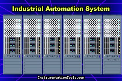
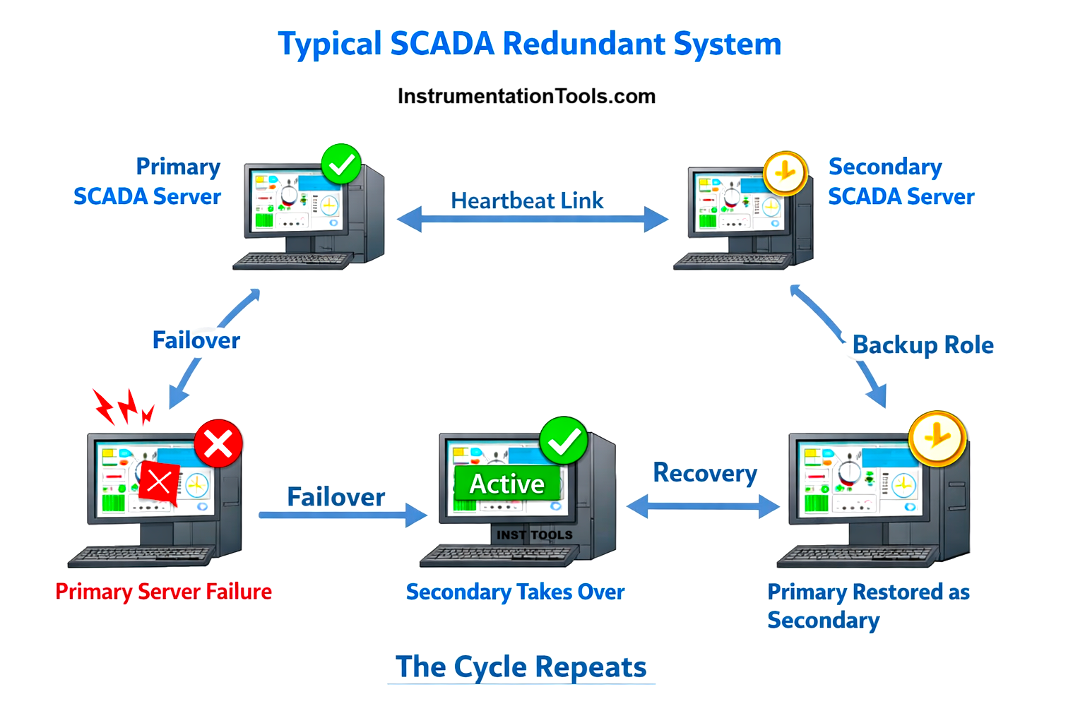
Refer to the image below. As you can see, any typical SCADA redundant system will look like this. Two servers will talk to each other, with one primary and the other as secondary. If the primary SCADA PC fails for any reason, the secondary PC will immediately take over and become the primary PC. When that failed primary PC has again been restored, then it will now become secondary and support the new primary PC as a backup. In this way, the cycle repeats. But this is a very upper idea and not a deep concept.
To understand how basic architectural redundancy works, first let us understand the architecture itself. The two PCs are having the communication drivers configured individually for the same PLC. So, the secondary PC is directly communicating with the PLC and working live in the plant. It does not directly collect data from the primary PC. Till this part, everything is clear. Let’s now understand the concept more properly with each topic.
Tags
The very first important part to understand is a tag. As discussed earlier, tags of a PLC are directly read by the secondary PC, as the PC too has the same backup running as the primary PC, with the communication path configured. So, the primary PC is not feeding tag values to the secondary PC. The user can only view the real-time tag values, but cannot perform any action with that tag in the secondary PC.
Alarms
The next part coming is an alarm. In a primary PC, the alarms will be evaluated by generating the event, assigning a timestamp, publishing these alarms to the clients, accepting acknowledgement and logging the alarm data continuously to an external database or historian server.
But, the secondary PC will only copy the current state of events, timestamp and other related internal context from the primary PC. It will not evaluate the alarms directly with the PLC; otherwise, there can be issues of time synchronisation, which will give different timestamps in both the PC, and it will break the rules of redundancy then.
So, when the primary PC fails, the secondary PC immediately takes over the alarm server from where it was stopped and resumes the operation from that state only by becoming primary. So, if the alarm is still active, it does not stamp the current time event and instead continues from the logged state, thus maintaining data reliability and avoiding duplication.
Trends
The functioning of a trend is the same as that of an alarm. The only difference is that trends also have real-time data, apart from historical trends. So in case of real-time trends, the secondary PC will take live tag value from PLC and show the graphics in live format. But, the historical trends remain with the primary PC, and it is the whole and sole master, as checked during alarms earlier. So, just apart from real trends, the historical trends perform the same as for an alarm condition, because it involves time stamping.
Reports
This is the last and major thing to be understood. Reports are logged mostly in an external database, like SQL Server, for example. Traditionally, as discussed earlier, a secondary PC will not be allowed to log data in the database. But what if the primary PC fails? The secondary PC takes over, but it should not be done on the local PC. Neither should the primary PC log data in its PC. Why, because communicating two database servers with each other for synchronisation is a very hectic task. The natural question will come that in case of a failover, the secondary PC should fetch all data from the primary PC. But this is practically very hard.
In this case, the solution is to log data in a third and central PC, called a historian PC traditionally. This is the best way to log report data, which will be done only by the primary PC. When it fails, then the secondary PC will take over and start dumping data to that server PC. In this case, data will be present in only one PC, and only the redundancy will happen in the sense of who will dump data in that server PC. If data were logged in individual PCs, then database replication will become complex, resolution will conflict, timestamp mismatches will occur, and the ambiguity of the report will be questioned.
If no external database is used and data is logged locally in individual PC’s, then too data logging will happen only in the primary PC. But to generate a complete report, the user must export data from the primary PC, export data from the secondary PC and combine them manually using Excel or SQL scripts. This is why auditors dislike this setup.
The final answer to conclude this topic is that:
- PLC is the single source of truth for tag values.
- Alarm ownership transfers during failover; alarm history does not restart.
- Trend visualisation is possible on both servers, but historical logging is single-writer.
- SCADA redundancy does not mean database replication between SCADA servers.
- In modern SCADA redundancy, both primary and secondary servers independently acquire PLC data, but only one server at a time has authority to generate alarms, log trends, and write reports; during failover, this authority transfers seamlessly without duplicating or synchronising historical data between servers.
- Across all major SCADA platforms, the redundancy concept is the same: both primary and secondary servers independently acquire data from PLCs, while only the active server has alarm, write, and historian authority. Vendors differ only in how strictly they restrict screens and user interaction on the standby node. And when the primary PC is working, a user is not allowed to operate anything from the secondary PC.