In this article, we will discuss about the Proximity sensor and Force & Pressure sensor and some of the types in Proximity and Force & Pressure sensor and their working natures and applications.
Proximity Sensor
A Proximity sensor is used to determine that an object is close to another object before contact is made. This noncontact sensing can be useful in many situations like counting the objects in a conveyor, position sensing of cylinders and measuring the speed of a rotor to navigate a robot.
There are many types of proximity sensors such as magnetic, eddy current and hall effect, optical, ultrasonic, inductive, and capacitive.
Types of Proximity Sensors
Following is some of the short discussion of types of proximity sensors:
- Magnetic Proximity Sensors
- Optical Proximity Sensors
- Ultrasonic Proximity Sensors
- Inductive Proximity Sensors
- Capacitive Proximity Sensors
- Eddy Current Proximity Sensors
1. Magnetic Proximity Sensors
Magnetic proximity sensors get activated when they are close to a magnet. They can be used for measuring rotor speeds and turning a circuit on or off. Magnetic proximity sensors may also be used to count the number of rotations of wheels and motors and therefore be used as a position sensor.
For example, in a mobile robot where the total displacement of the robot is calculated by counting the number of times a particular wheel rotates multiplied by the circumference of the wheel.
A magnet is placed on the wheel or on its shaft for finding the wheel rotations with the help of a magnetic proximity sensor and having the sensor stationary on the chassis. Similarly, these sensors are used for some other applications, including safety.
Example: Many devices have a magnetic proximity sensor that sends a signal when the door is open to stop the rotating or moving parts.
2. Optical Proximity Sensors
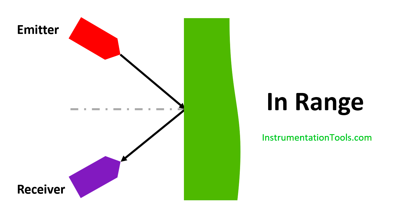
Optical proximity sensors consist of a light source called an emitter and a receiver. This receiver senses the presence or absence of light. The receiver is usually a phototransistor and the emitter are usually a LED.
This phototransistor and LED combined to form a light sensor are usually many applications like optical encoders.
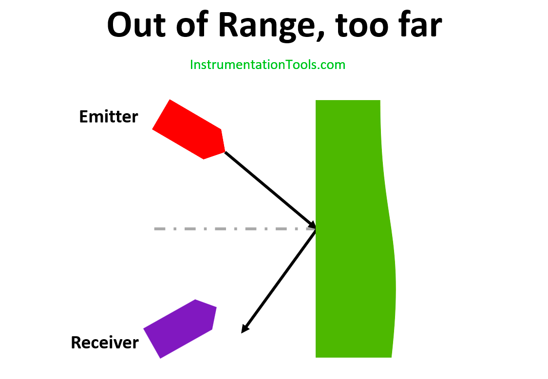
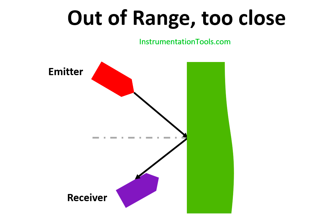
As a proximity sensor, it is set up such that light, emitted by the emitter is not reflected to the receiver unless an object is within range. If the reflective object is not within the range, the light is not seen by the receiver, therefore there will be no signal.
In this optical proximity sensor, the no signal situation will be happened twice, when the receiver is out of the range or not within the range means the signal will not be produced. If the receiver is in the short-range also there will be no signal. So, the placement of the receiver in this sensor plays an important thing.
Alternative Optical Proximity Sensor
There is another variation in the optical proximity sensor, in this system, it can determine both proximities as well as the short-range distance measurement.
A beam of light is passed through a prism that refracts the light into its constituent primary colors.
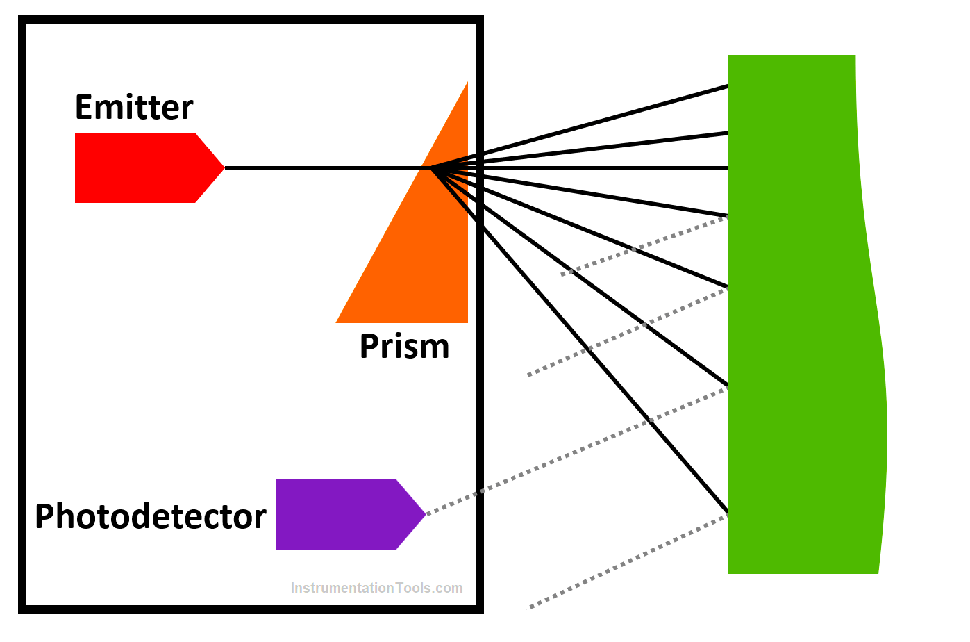
Depending on the object’s distance from the sensor, one particular color of light is reflected back to the sensor’s photodetector. The distance can be found by measuring the energy of the reflected light.
3. Ultrasonic Proximity Sensors
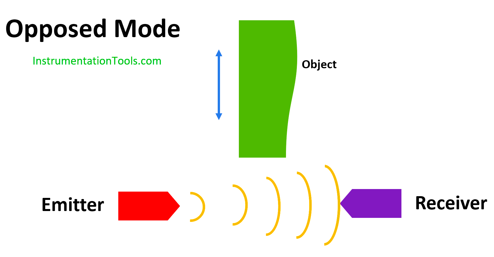
In an Ultrasonic proximity sensor, an ultrasonic emitter emits frequent bursts of high-frequency soundwaves. This Ultrasonic sensor works with two modes, echo mode and opposed mode.

In opposed mode, a receiver is placed in front of the emitter; in echo mode, the receiver is placed either next to the or integrated into the emitter which receives the sound wave. If the receiver is within the range or the sound which is reflected by a surface close to the sensor, it is sensed and a signal is produced. If the receiver is out of range, it will not get sensed and there will be no signal.
All ultrasonic sensors have a blind zone near the surface of the emitter in which the distance and presence of an object cannot be detected. Surfaces such as rubber and foam do not reflect the soundwaves in that surfaces Ultrasonic sensors are not used.
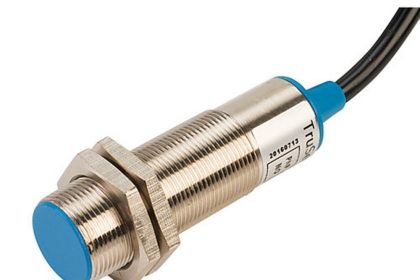
4. Inductive Proximity Sensors
Inductive sensors are mostly used for detecting metal surfaces. This inductive sensor is made up of a coil, a ferrite core, an oscillator/detector, and a solid-state switch.
In the presence of a metal object in the surrounding of the sensor, the amplitude of the oscillator diminishes which makes the detector to sense the change and turn the solid state switch off and then produce the signal. When the part leaves the range of the sensor, it turns on again which makes the signal to cut.
5. Capacitive Proximity Sensors
The capacitive sensor reacts to the presence of any object that has a dielectric constant of more than 1.2. If the material has a dielectric constant of more than 1.2 is within the range, the capacitance of the material raises the total capacitance of the circuit.
An increase in capacitance rises the internal oscillator to turn on the output unit which will send out an output signal.
Similarly, the sensor can detect the presence of an object within a range. Capacitive sensors can sense non-metals like wood, liquids, and even chemicals. Below are some of the material’s dielectric constants.
| Material | Dielectric Constant |
| Air | 1 |
| Aqueous Solution | 50-80 |
| Epoxy Resin | 2.5-6 |
| Flour | 1.5-1.7 |
| Glass | 3.7-10 |
| Nylon | 4-5 |
| Porcelain | 4.4-7 |
| Cardboard | 2-5 |
| Rubber | 2.5-3.5 |
| Water | 80 |
| Dry Wood | 2-7 |
| Wet Wood | 10-30 |
6. Eddy Current Proximity Sensors
When a conductor is placed in a changing magnetic field, an electromotive force is induced in the conductor that causes a current to flow in the material. This current is called eddy current.
An eddy current sensor has typically two coils, where one coil generates a changing magnetic field as a reference. In the close of proximity of conducting materials, an eddy current is produced in the material which produces a magnetic flux opposite of the first coil, resulting in reducing total flux.
The change in total flux determines the proximity of the conducting material and is measured by the second coil. Eddy current sensors are used to detect the presence of conductive materials as well as the non-destructive testing of voids and cracks, and thickness of materials.
Force and Pressure Sensors
Force and pressure sensors are used to determine the force applied to the object which involves the generation of high voltages, intruder alarms, microwave ovens, load cells, etc.
In general, there are many force and pressure sensors are using in many practical applications.
Following are some of the major force and pressure measurement sensors:
- Piezoelectric Sensors
- Force Sensing Resistor
- Strain Gauge
- Antistatic Foam
1. Piezoelectric Sensors
Piezoelectric material generally compresses if exposed to a voltage and produces a voltage if compressed. This was used in devices such as record players to create a voltage from the variable pressure caused by the grooves in the record.
Similarly, a piece of piezoelectric can be used to measure pressure or force in robotics. It will produce a voltage that can be used for further use or for some application use, but it needs to be conditioned and amplified for use.
2. Force Sensing Resistor
The Force sensing Resistor is a polymer thick film device that exhibits a decreasing resistance with increasing force applied perpendicular to its surface.
In this resistor, a resistance of 500kΩ can be decreased up to 1kΩ for the force of 10G of force.
3. Strain Gauge
A strain gauge can also be used to measure force. The output of the strain gauge is a variable resistance, proportional to the strain, which itself is a function of applied forces. So, by measuring resistance we can measure the force applied to it.
Strain Gauges are mainly used in load cells for measuring the amount of load in the part. Strain gauges are used within a Wheatstone Bridge. A balanced Wheatstone bridge has similar potentials at points A and B
If the resistance in any of the four resistors changes, there will be a current flow between these two junctions. At the same time, we need to calibrate the bridge for zero flow in the galvanometer. When under stress, the value of the resistance will change causing an imbalance in the Wheatstone bridge and the current flow.
So, to overcome that we need to adjust the value of the resistance of the others until the current flow becomes zero. The change of resistance in the strain gauge can be calculated by
R1/R4 = R2/R3
Strain gauges are sensitive to temperature change. So, we need to use this strain gauge in proper temperature conditions. To overcome this a dummy strain gauge is used for compensating the change in resistance while there is a change in temperature.
4. Antistatic Foam
The antistatic foam used for transporting IC Chips is conductive and its resistance changes due to an applied force. It can function as crude and simply though it is inexpensive.
For using antistatic foam, a pair of wires is inserted into the two sides of the part and measure the voltage and resistance across it. The change in resistance will be used for calculating the force on it.