Pressure is considered a basic measurement because it is utilized in several process applications for measurement of different process variables such as : pressure, differential pressure, flow, level, density, etc.

Pressure Transmitter Applications
1.1 Differential Pressure
Differential pressure is the difference in magnitude between some pressure value and a reference pressure. In a sense, absolute pressure can also be considered a differential pressure, with full vacuum or zero absolute as the reference pressure. Gauge pressure too can be considered a differential pressure, since in gauge pressure the atmospheric pressure is the reference pressure.
1.2 Flow
A common application of a Differential Pressure transmitter is for sensing flow rate. A primary flow element such as the one shown in Figure 4-1 has an internal restriction. This restriction reduces the cross sectional area of the pipe through which the process flows. This restriction causes fluid velocity to increase as it passes by the restriction. Therefore, fluid immediately upstream from the restriction has a lower kinetic energy (speed) than the fluid immediately downstream from the restriction. This increase in kinetic energy across the restriction is balanced by a corresponding decrease in potential energy (static pressure). Taps placed on either side of the restriction sees a differential in static pressure produced as a result of this decrease in potential energy of the fluid.
Example: The differential pressure transmitter subtracts the downstream or lesser pressure from the upstream pressure. This pressure difference is generally quite low, typically from 1″ water column to 750″ water column (0.24 to 186 KPa) depending on the fluid and flow rate. A generic representation of a differential pressure flow measurement is shown in Figure 2.
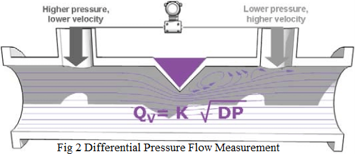
The output of a transmitter measuring the flow rate by means of an obstruction in the stream is not linear with flow. To make the signal linear with flow, it is necessary to perform an arithmetic conversion by extracting the square root of the pressure difference signal.Electronic differential pressure transmitters are available with square root extraction electronics built into the instrument.
1.3 Liquid level
Liquid level measurements can be made using a differential pressure type transmitter or gauge pressure type transmitter. Typically, this is determined based upon whether the tank is open to the atmosphere or whether it is closed.
1.3.1 Open tank
Open tank liquid level measurement means that the tank is open to the atmosphere. In open tank applications, any change in atmospheric pressure affects the process fluid pressure within the tank. In this type of level measurement application, the low side of the transmitter measures atmospheric pressure, thus cancelling out the effects of atmospheric pressure on the tank fluid level. The high side of the transmitter is connected to the tank and thus measures the actual level of fluid in the tank.
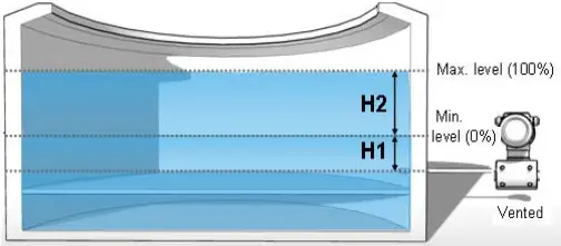
When the level to be measured is of an Open Tank, a gauge transmitter is usually indicated. It can be single or double port, the single port is less expensive, but a double port can be necessary because of the low gauge pressure ranges required.
The DP range calculation follows:
Lower range value = [H2*Gl]
Upper range value = Lower range value + H1*Gl
Where
Gl = specific gravity of process liquid
1.3.2 Closed tank
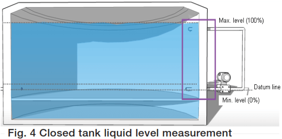
A closed tank application is where the tank or vessel is sealed from the atmosphere. As process fluid fills or is emptied from the tank, the pressure inside the tank may go from positive to vacuum. This change in internal tank pressure has a direct effect on measured fluid level, unless it is compensated for. Piping the low side of a differential pressure transmitter to the top of the tank easily does this.
Dry Leg Calculation
When the level to be measured is of a Closed Tank, a differential transmitter is necessary. The DP range calculation follows:
Lower range value = [H2*Gl]
Upper range value = Lower range value + H1*Gl
Where
Gl = specific gravity of process liquid
Wet leg Calculation
Lower range value = [H2*Gl] – H4*Gw,
Upper range value = Lower range value + H1*Gl
Where
Gl = specific gravity of process liquid
Gw = specific gravity of wet leg fluid
In case of Remote Seal, the range calculation is according to the following formula:
Lower range value = H1 x SG – H3 x SGc,
Upper range value = Lower Range Value + H2 x SG
Where
SG = specific gravity of process liquid
SGc = specific gravity of liquid in capillary
1.3.3 Calculations Example
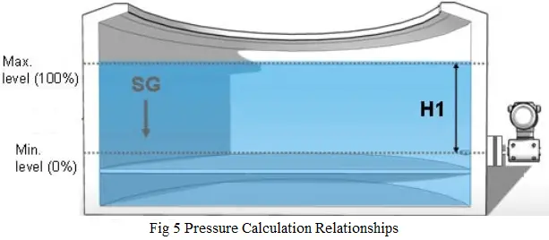
To calculate the pressure at the bottom of the tank is necessary to know the value of h1 in cm or inches (Figure 5). For example, if h1 is 14″, and the material in the tank is water, then we can express the pressure at the bottom as 14″ H20.
But if the liquid in the tank is not water, a conversion must be made to specify in “H20. The formula to do this is:
h = (h”) x (SG)
Where:
h = liquid head, H20
h” = Actual liquid head, in inches
SG = Specific Gravity (dimensionless) of the fluid in the tank
Specific Gravity (SG) is the relative weight of a unit volume of liquid compared to the same volume of water. Gasoline, for example, has a SG of approximately 0.8. Therefore, a litre of gasoline weighs 8/10 or 80% of the weight of a litre of water.
Consequently, when specifying the pressure of the liquid column in a tank, it is necessary to identify the liquid and obtain its SG.
1.3.4 Bubble tube Level measurement
Another method of liquid level measurement is by means of a bubble tube or bubble pipe, Figure 6. This may be applied to either an open or closed tank.
A constant pressure of air or a gas compatible with the tank contents is maintained on the pipe inserted into the tank. As the level changes, the back pressure measured by the transmitter is a direct level measurement. The advantage is that only the pipe material is exposed to the process – not the transmitter. However, the process cannot be sensitive to a gas bubbling through it.
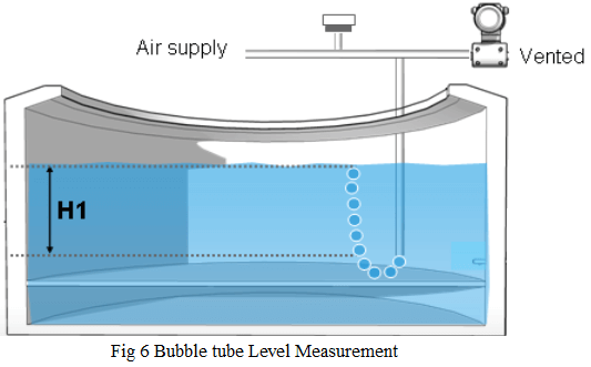
The DP range calculation is following:
Lower range value = minimum orifice back pressure
Upper range value = Lower range value + H1*Gl
Where
Gl = specific gravity of process liquid
1.4 Interface level measurement
Interface level measurement, i.e., measuring the liquid level of an interface between two separated liquids such as oil and water can be made also using the differential pressure transmitter shown in Figure 7.
Liquids 1 and 2 are of different densities and as long as the total level in the tank is above the top tap, and as long as the distance h remains constant, the change in density, and hence the hydrostatic pressure, will change with interface level change.
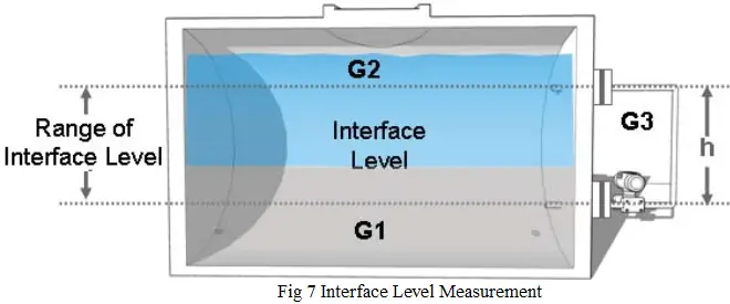
This measure can be applied either in open or closed tanks, or with clean or dirty fluids. The selection of the suitable type of instrument, including flange mounted or remote seals, is the same as for the level measurement.
While the DP range calculation is following:
Lower range value = H1*(SG1 – SGc)
Upper range value = Lower range value + H1*(SG2 – SGc)
Where
SG1 = lower specific gravity
SGc = specific gravity of liquid in capillary
SG2 = higher specific gravity liquid
1.5 Density measurement
The preceding principle leads to density measurement in a tank. In this case, a homogeneous liquid of changing density in the tank will exert varying pressure on the transmitter depending on the change in density.
As long as the level remains above the top tap, and as long as h is constant the transmitter will respond to changes in density. Density is weight per unit volume, e.g., Kilograms per cubic meters. If the density increases, the pressure on the lower tap increases and so does the transmitter output. Typically, as in level measurement, a differential pressure transmitter is used because the spans are relatively low.
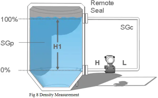
This measure can be applied either in open or closed tanks, or with clean or dirty fluids. The selection of the suitable type of instrument, including flange mounted or remote seals, is the same as for the level measurement. While the DP range calculation is following:
Lower range value = H1 x (SGpl – SGc)
Upper range value = Lower range value + H1 x (SGph – SGpl))
Where
SGpl = minimal specific gravity of process liquid
SGc = specific gravity of liquid in capillary
SGph = maximal specific gravity of process liquid
1.6 Volume (of product in a tank)
Once determined the level of product in a Tank it is possible to calculate the Volume of the process fluid. If the relationship between the volume and the measured level is linear for tanks with a cylindrical shape, this is not true for other shapes.
Also Read: Basics of Pressure