In some cases, after isolating a fault to a particular circuit, it may be necessary to isolate the problem to a single component in the circuit.
In this event, you have to apply logical thinking and your knowledge of the symptoms caused by certain component failures.
Some typical component failures and the symptoms they produce are now discussed.
A half-wave filtered rectifier with an open diode is shown in Below Figure. The resulting symptom is zero output voltage as indicated.
This is obvious because the open diode breaks the current path from the transformer secondary winding to the filter and load resistor and there is no load current.
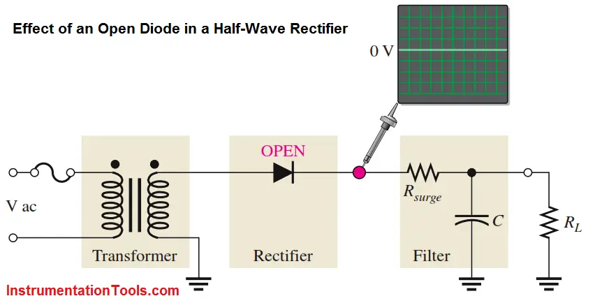
Fig : The effect of an open diode in a half-wave rectifier is an output of 0 V.
Other faults that will cause the same symptom in this circuit are an open transformer winding, an open fuse, or no input voltage.
A full-wave center-tapped filtered rectifier is shown in Below Figure. If either of the two diodes is open, the output voltage will have twice the normal ripple voltage at 50/60 Hz rather than at 100/120 Hz, as indicated.
Fig : The effect of an open diode in a center-tapped rectifier is half-wave rectification and twice the ripple voltage at 50HZ / 60HZ.
Another fault that will cause the same symptom is an open in the transformer secondary winding. The reason for the increased ripple at 60 Hz rather than at 120 Hz is as follows.
If one of the diodes in Above Figure is open, there is current through RL only during one half-cycle of the input voltage. During the other half-cycle of the input, the open path caused by the open diode prevents current through RL.
The result is half-wave rectification, as shown in Above Figure, which produces the larger ripple voltage with a frequency of 60 Hz.
An open diode in a full-wave bridge rectifier will produce the same symptom as in the center-tapped circuit, as shown in Below Figure.
The open diode prevents current through RL during half of the input voltage cycle. The result is half-wave rectification, which produces double the ripple voltage at 60 Hz.
Fig : Effect of an open diode in a bridge rectifier.
Three types of defects of a filter capacitor are illustrated
An open primary or secondary winding of a power supply transformer results in an output of 0 V, as mentioned before.
In this post, we will learn the basic requirements for a network switch to be…
The PLC panel and MCC panel interface signals are start, stop, run feedback, trip, local…
In this article, we are going to discuss about shutter door control using induction motor…
Electrical Drives control the motion of electric motors. Motion control is required in industrial and…
PLC ladder logic design to control 3 motors with toggle switch and explain the program…
VFD simulator download: Master the online tool from the Yaskawa V1000 & programming software for…


View Comments
Good informative
Very educative