A water storage vessel is elevated by a tower structure, to provide a natural source of water pressure to all points of use below:
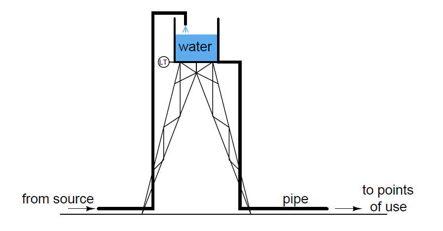
A pressure-sensing level transmitter is presently located at the base of the vessel, at the top of the tower structure, to measure water level inside the vessel.
It has a calibrated range of 0 to 10 feet (0 to 120 inches W.C.). Unfortunately, the water inside the transmitter sometimes freezes in the winter months, preventing operation of the level measurement system.
The water inside the storage vessel and the large pipes never freezes, because there is enough circulation as a result of water usage to raise the temperature and prevent ice crystals from forming.
It is decided to move the transmitter to ground level, at the base of the tower, so that it may be located inside a small, heated shelter where it will never freeze.
By connecting the transmitter directly to the large water pipe carrying water from the vessel to the points of use, the hydrostatic pressure will still be measurable at this point:
Calculate the new calibration points (lower and upper range-values) for the transmitter in its new location.
Also calculate the water level in the vessel when the transmitter output is 13.7 mA, and the amount of hydrostatic pressure at that point in units of PSI.
Finally, identify whether the transmitter move resulted in a shift of its zero, a shift in its span, or both.
Answer:
Lower range-values: 100 feet W.C. input (1200 inches W.C.) = 4 mA output
Upper range-values: 110 feet W.C. input (1320 inches W.C.) = 20 mA output
Water level in vessel at 13.7 mA = 6.0625 feet ; applied pressure = 45.98 PSI
Share your answers & explanation with us through the below comments section.
Read Next:
Credits: Tony R. Kuphaldt
In this article, we are going to discuss about shutter door control using induction motor…
Electrical Drives control the motion of electric motors. Motion control is required in industrial and…
PLC ladder logic design to control 3 motors with toggle switch and explain the program…
VFD simulator download: Master the online tool from the Yaskawa V1000 & programming software for…
The conveyor sorting machine is widely used in the packing industries using the PLC program…
Learn the example of flip-flop PLC program for lamps application using the ladder logic to…

