This article discusses the PLC System Forward and Reverse program with repetition using the Siemens TIA Portal. The system can only be started if the system “Repeat” parameter has been set. This system runs automatically; the system will run in Forward mode for a certain time and will change to Reverse mode after a certain time. This process will continue to repeat according to the number of “Repetitions” that have been previously set.
Program Objective
System Sequence:
- The Repetition parameter value (Set Value) must be provided.
- The system will run when the Start button is Pressed.
- Forward Mode will be active for 5 seconds.
- Then switch to Reverse mode for 7 seconds.
- Data (Process Value) Repetition will increase (+1).
- The Forward and Reverse mode cycles are repeated at the same time interval.
- The system will stop when the (Process Value) and (Set Value) Repetition values are Equal.
- Data (Process Value) Repetition will be Reset.
- Or, the system will stop if the Stop button is Pressed.
Siemens TIA Portal
Project I/O Details
| S.No. | Comment | Input (I) | Output(Q) | Memory Word | Memory Bits | Timer |
| 1 | START_SYSTEM | I0.0 | ||||
| 2 | STOP_SYSTEM | I0.1 | ||||
| 3 | FORWARD | Q0.0 | ||||
| 4 | REVERSE | Q0.1 | ||||
| 5 | TIMER1 | DB1 | ||||
| 6 | TIMER2 | DB2 | ||||
| 7 | SYSTEM_ON | M0.0 | ||||
| 8 | LOOP_CUTOFF | M0.1 | ||||
| 9 | IR_TIMER1 | M0.2 | ||||
| 10 | IR_TIMER2 | M0.3 | ||||
| 11 | IR_TIMER2.1 | M0.4 | ||||
| 12 | PV_LOOP | MW1 | ||||
| 13 | SV_LOOP | MW2 |
Motor Forward Reverse PLC Logic
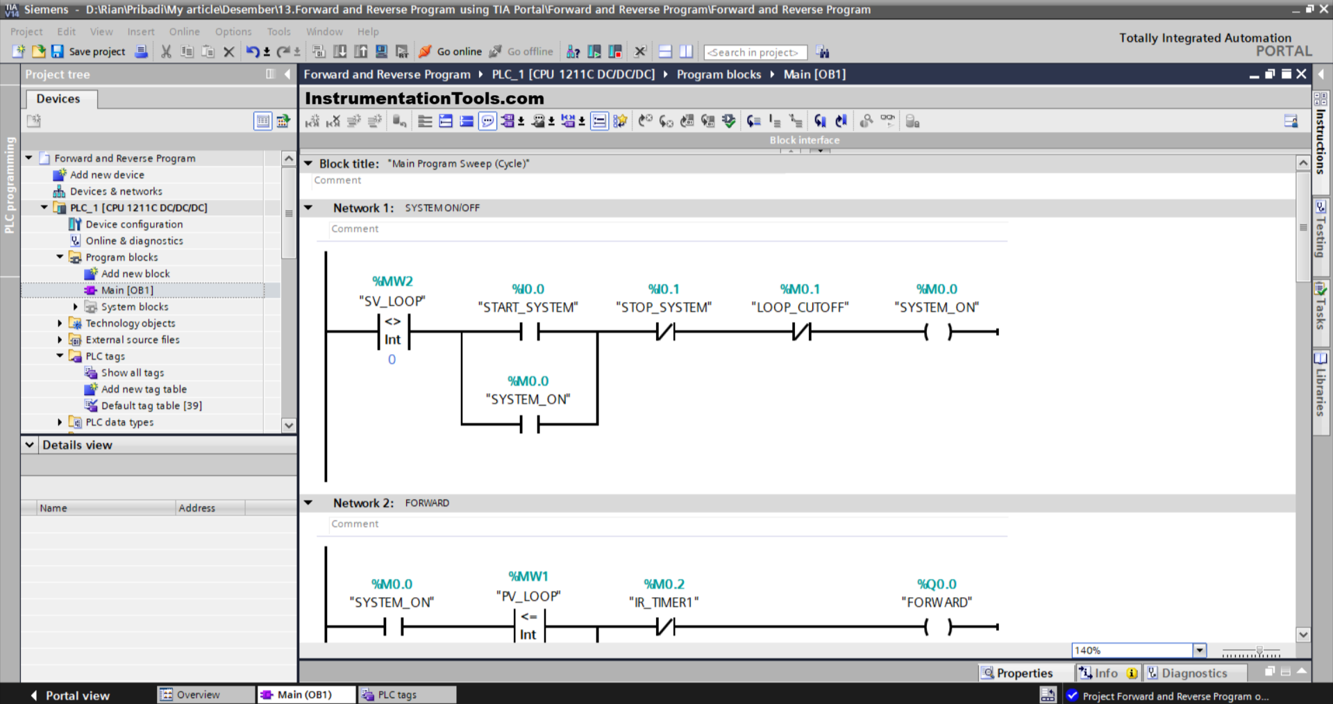
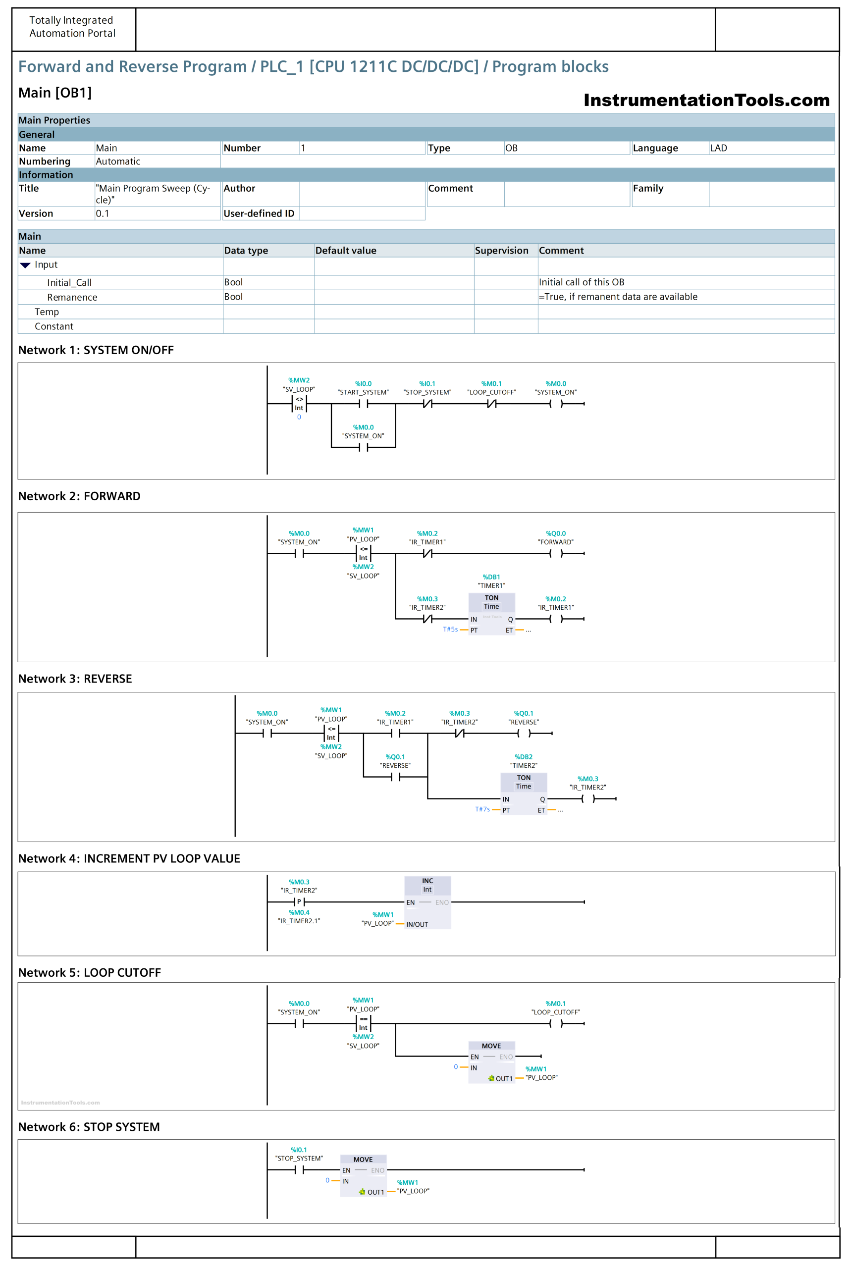
NETWORK 1 (SYSTEM ON/OFF)
In this network, when the value in the memory word SV_LOOP (MW2) is Not Equal to zero “0” and the START_SYSTEM (I0.0) button is Pressed, the memory bit SYSTEM_ON (M0.0) will be in the HIGH state. Because it uses Latching, even though the START_SYSTEM (I0.0) button has been Released the memory bit SYSTEM_ON (M0.0) will remain in the HIGH state.
If the STOP_SYSTEM (I0.1) button is Pressed or the NC contact of the memory bit LOOP_CUTOFF (M0.1) is in the HIGH state, then the memory bit SYSTEM_ON (M0.0) will be in the LOW state.
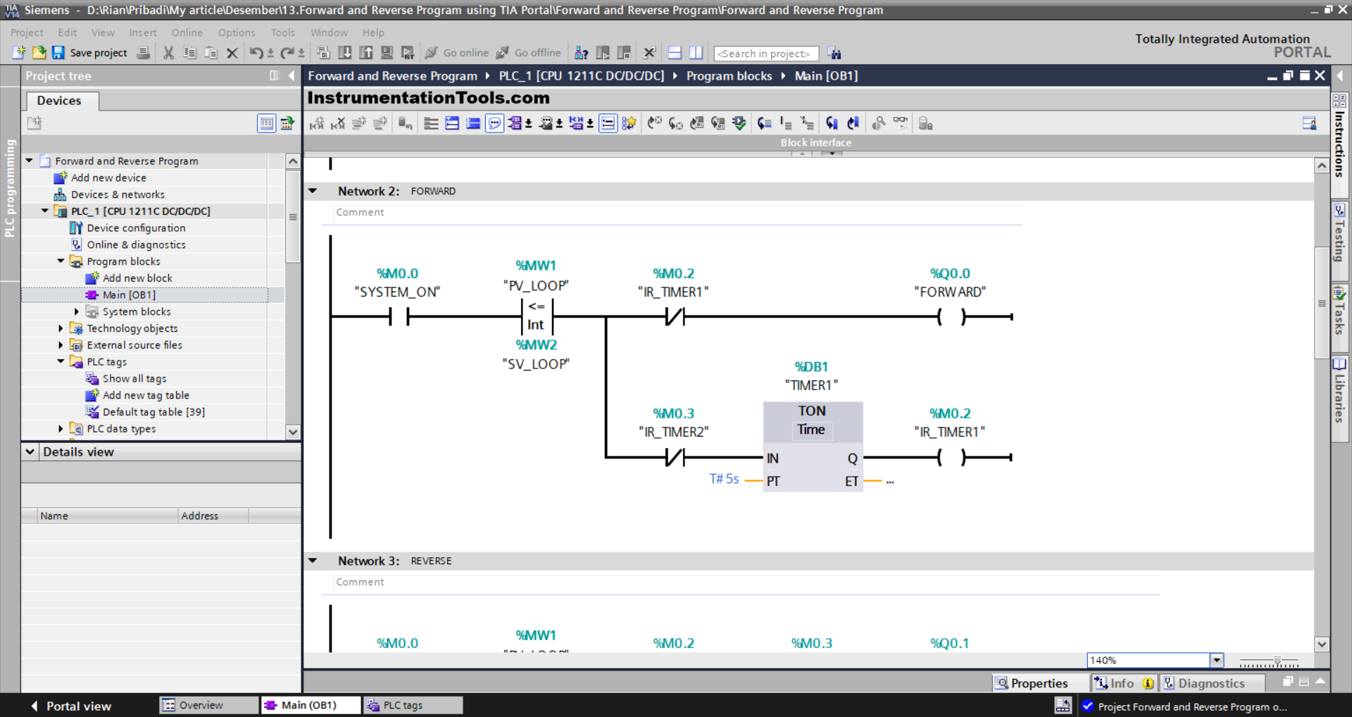
NETWORK 2 (FORWARD)
In this network, if the NO contact of the memory bit SYSTEM_ON (M0.0) is in the HIGH state and the value of the memory word PV_LOOP (MW1) is Less Than Or Equal to SV_LOOP (MW2), then the FORWARD (Q0.0) output will be ON.
Timer TIMER1 (DB1) will count up to 5 seconds, After Timer TIMER1 (DB1) has finished counting, the memory bit IR_TIMER1 (M0.2) will be in the HIGH state.
The FORWARD (Q0.0) output will be OFF due to the Interlock of the memory bit IR_TIMER1 (M0.2).
Or, the FORWARD (Q0.0) output will be OFF and the TIMER1 (DB1) timer will be reset if the NC contact of the memory bit IR_TIMER2 (M0.3) is in the HIGH state or if the memory word PV_LOOP (MW1) is Greater Than SV_LOOP (MW2).
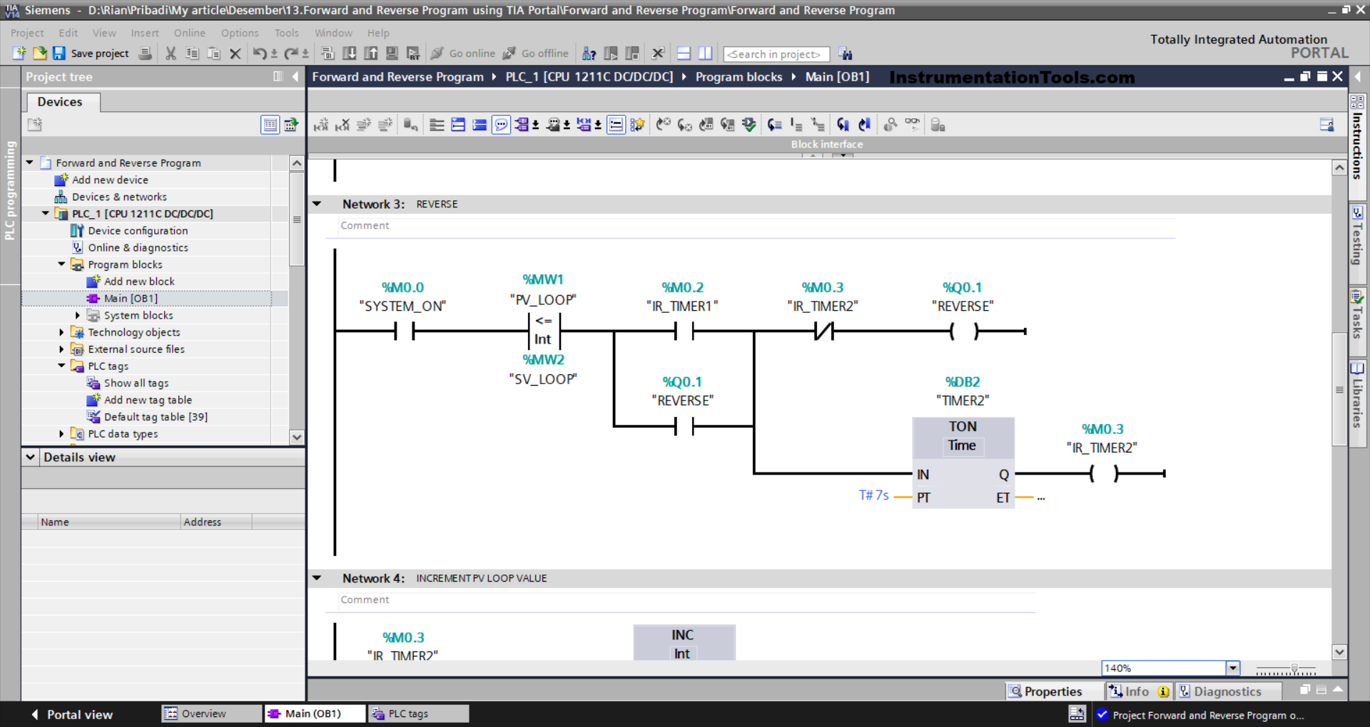
NETWORK 3 (REVERSE)
In this network, if the NO contacts of the memory bits SYSTEM_ON (M0.0) and IR_TIMER1 (M0.2) are in the HIGH state and the value in the memory word PV_LOOP (MW1) is Less Than Or Equal to SV_LOOP (MW2), then the output REVERSE (Q0.1) will be ON.
The REVERSE (Q0.1) output will remain ON even though the NO contact of the memory bit IR_TIMER1 (M0.2) is in the LOW state, because it uses Latching.
The TIMER2 (DB2) timer will count up to 7 seconds. After Timer TIMER2 (DB2) has finished counting, the memory bit IR_TIMER2 (M0.3) will be in the HIGH state.
When the NC contact of the memory bit IR_TIMER2 (M0.3) is in the HIGH state or if the value of the memory word PV_LOOP (MW1) is GREATER THAN SV_LOOP (MW2), then the output REVERSE (Q0.1) will be OFF.
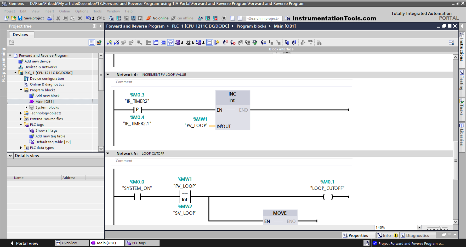
NETWORK 4 (INCREMENT PV LOOP VALUE)
The value in memory word PV_LOOP (MW1) will increase (+1) when the NO contact of memory bit IR_TIMER1 (M0.2) is in the HIGH state.
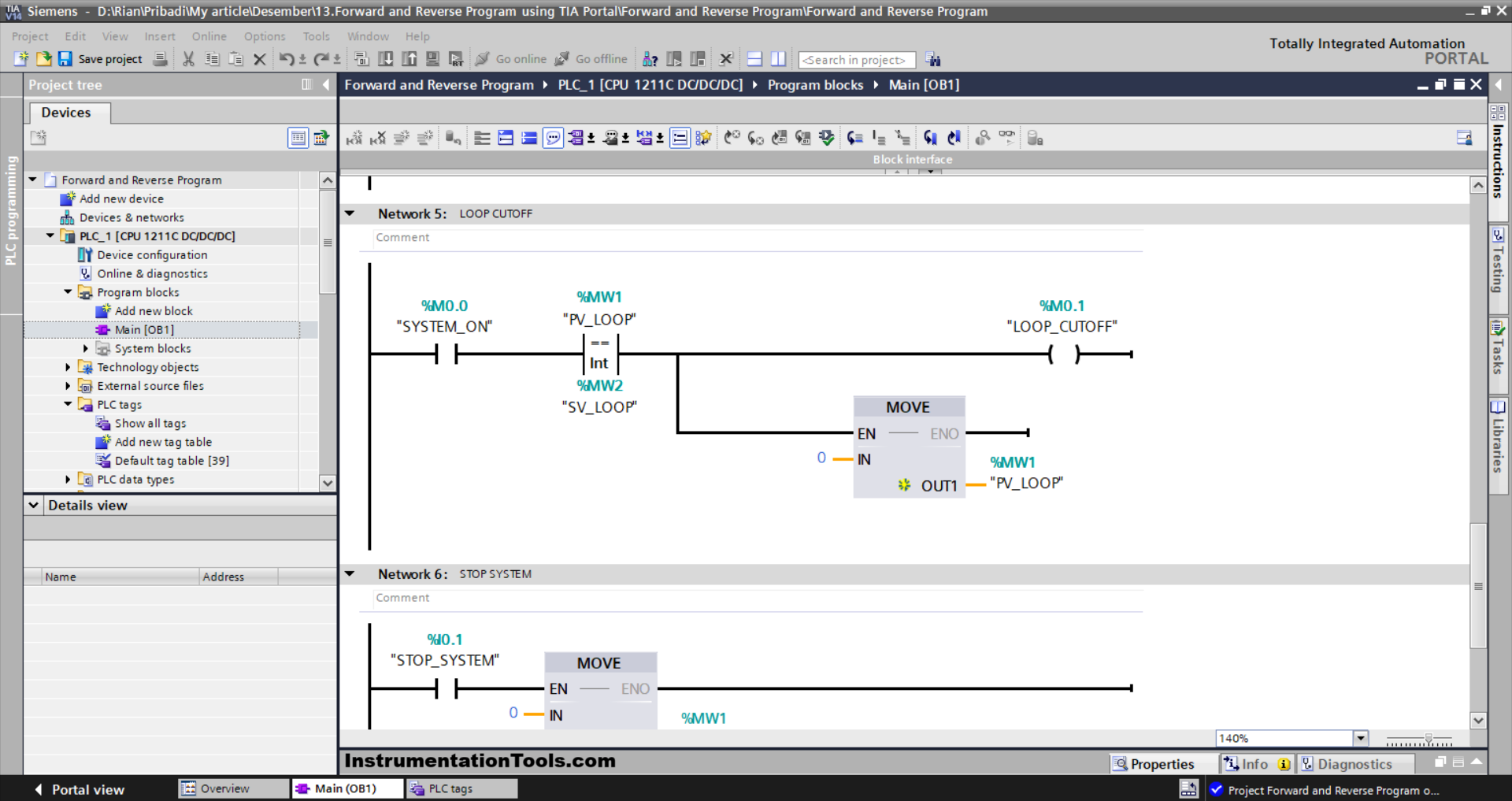
NETWORK 5 (LOOP CUTOFF)
In this network, when the memory bit SYSTEM_ON (M0.0) in the HIGH state and the value in the memory word PV_LOOP (MW1) Equal to SV_LOOP (MW2), then the memory bit LOOP_CUTOFF (M0.1) will become HIGH state and the memory word PV_LOOP (MW1) becomes zero value “0”.
The MOVE instruction moves the zero value “0” to the memory word PV_LOOP (MW1).
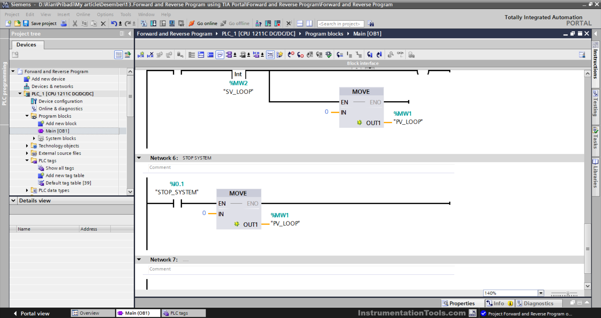
NETWORK 6 (STOP SYSTEM)
The value in memory word PV_LOOP (MW1) becomes zero “0” when the STOP_SYSTEM (I0.1) button is Pressed.
The MOVE instruction moves the zero value “0” to the memory word PV_LOOP (MW1).
Read Next:
- Electric Motor Repeat Cycle PLC Logic
- PLC Instruction List Level Control of Tank
- Simple Conveyor Control PLC Programming
- Rules for Writing SCL Language in Tia Portal
- Structured Text Program for Light Sequences


If it possible can you post a video for siemens s7-300 plc as master and delta plc as slave communication with each other.It helps to learn more