Build the ladder logic example with Timers to turn ON/OFF the lamp using push buttons with respect to program logic conditions.
PLC Logic
1. Start PB and Stop PB are to turn ON and OFF the lamp.
2. After Start PB is pressed,
- In the following sequence Outputs should turn ON/OFF
- Q1 is turn ON for 5 sec
- Q2 is turn ON for 5 sec
- Q3 is turn ON for 5 sec
- Q4 is turn ON for 5 sec
3. End of above sequence will trigger,
- All four outputs (Q5, Q6, Q7, Q8) to turn ON.
- In the following sequence, outputs should turn OFF after its turned ON,
- After 5 sec, Q5 should go OFF
- After 5 sec, Q6 should go OFF
- After 5 sec, Q7 should go OFF
- After 5 sec, Q8 should go OFF
Note: Process should continue until stop PB is pressed
List of Inputs and Outputs
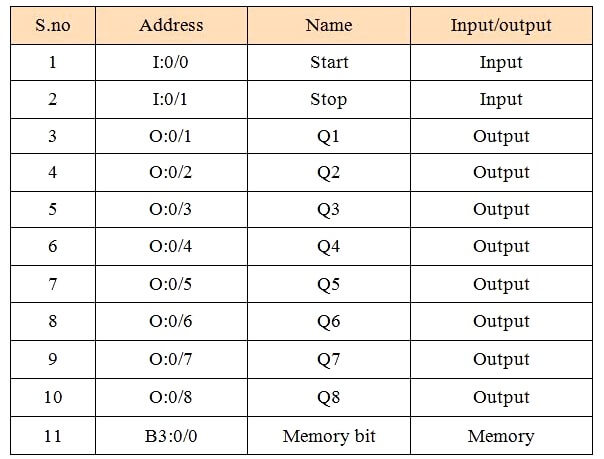
Ladder Logic Example with Timers
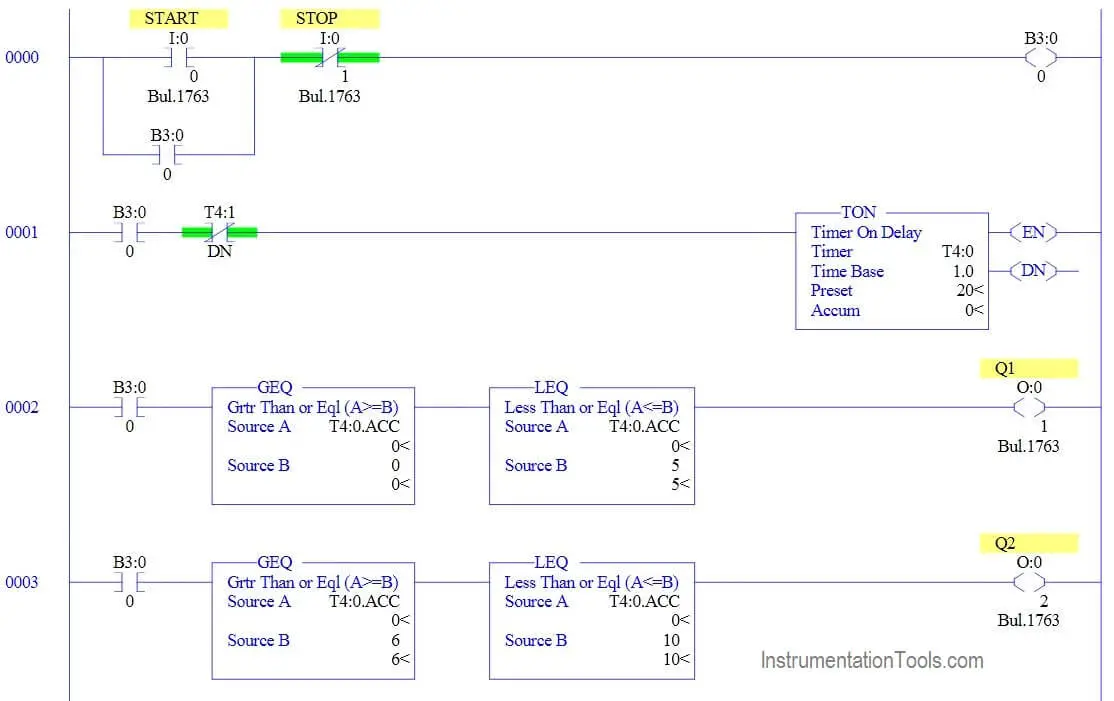
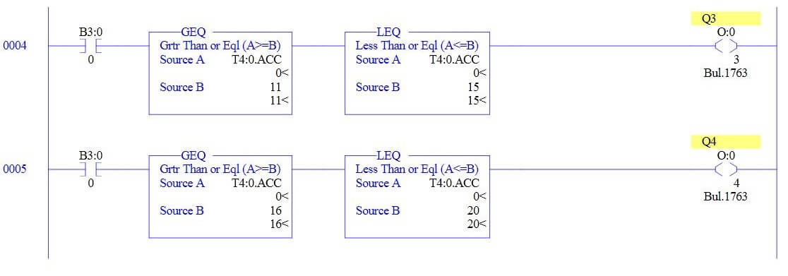
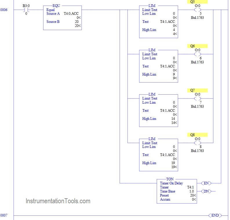
Logic Description
RUNG 0000
Latching rung to operate the system through Master Start and Stop PB.
RUNG 0001
Latched B3:0/0 is connected with T4:0 which starts running. Normally closed contact of T4:1 timer done bit is connected to make the process continue until stop PB is pressed.
RUNG 0002
Greater than or equal and Less than or equal block is connected in series with Q1 (O:0/0),When accumulator value between 0 to 5 triggers Q1 turns ON.
RUNG 0003
Greater than or equal and Less than or equal block is connected in series with Q2 (O:0/1),When accumulator value between 6 to 10 triggers Q2 turns ON.
Rung 0004
Greater than or equal and Less than or equal block is connected in series with Q3 (O:0/2),When accumulator value between 11 to 15 triggers Q3 turns ON.
Rung 0005
Greater than or equal and Less than or equal block is connected in series with Q4 (O:0/3),When accumulator value between 16 to 20 triggers Q4 turns ON.
Rung 0006
When T4:0 accumulator value reaches 20,outputs Q5.Q6,Q7 & Q8 turns ON along with timer T4:1 which presets for 20 second. Limit block is used turn OFF each output in respective sequence.
Each Limit block check with T4:1’s accumulator value, when it’s not in the limit its triggers the output to turn OFF.
Conclusion:
The above explained ladder logic for lamp turn ON/OFF is for example only. We can use this example program to understand the working of Push Buttons, Timers and Limit block in Allen Bradley PLC.
If you liked this article, then please subscribe to our YouTube Channel for PLC and SCADA video tutorials.
You can also follow us on Facebook and Twitter to receive daily updates.
Read Next:
