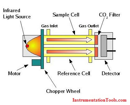
The CO2 Analyser is a Analytical instrument that measures the concentration of CO2 gas in the process. The CO2 Analyzer use multi-component analysis by using Non Dispersive Infrared (NDIR) sensor technology for consistent, precise process gas measurement.
The Non Dispersive Infrared (NDIR) detection method is based upon the absorption of infrared radiation at specific wavelengths as it passes through a volume of sample. Non-Dispersive Infrared (NDIR) techniques for the measurement of various gases rely on the energy absorption characteristics of a particular gas in the infrared region. In a simple NDIR instrument, Infrared energy passes through two identical tubes and falls on a detector. The first tube is the reference cell and is filled with a non-absorbing gas such as nitrogen. The second tube is the measurement cell and contains the gas sample to be analyzed.

The IR Source continuously sends an IR waves through the gas tubes and detector measures the intensity of two different wavelengths, one at the sample gas absorption wavelength and the other is at reference gas absorption wavelength. As the reference gas generally contains nitrogen so the detector receives 100% signal. If the CO2 gas is present in sample gas means the received signal will be attenuated at the detector side. The detector measures these two signals and their difference is proportional to the amount of absorbing gas in the sample cell .i.e. CO2 gas. So Finally the CO2 gas concentration is measured with the difference in absorption of IR radiation in the sample and reference cells. CO2 gas concentration measuring unit is ppm.
Also See: NDIR Gas Analyzer Animation
The PLC panel and MCC panel interface signals are start, stop, run feedback, trip, local…
In this article, we are going to discuss about shutter door control using induction motor…
Electrical Drives control the motion of electric motors. Motion control is required in industrial and…
PLC ladder logic design to control 3 motors with toggle switch and explain the program…
VFD simulator download: Master the online tool from the Yaskawa V1000 & programming software for…
The conveyor sorting machine is widely used in the packing industries using the PLC program…
View Comments
Infrared Non Dispersive ,(NDIR), CO2 gas analyzer working principle is elaborate and informative. Thank you very much.
Hi Shaju,
Thanks for the encouraging comments. More will be updated soon. Keep in touch.
Dear sir, i like it for analyzer. Please post all analyzer instruments information.
thank you
So many interesting posts i read here on instrumentation, Thank You.
This is best in easy way information given by you sir thank you...
Very good
it is really very informative, but i want to know more about detector and the chopper used in this type of analyzer.like i read that at detector resonance is created, why? and why is this chopper used in analyzer?
Hello Sandeep, Chopper is used to split the source for reference cell and sample cell as shown in above figure. Concept is same.
Hiii S bharadwaj
Actually the source is split before chopper as u can see it in the image "Typical infrared Photometer" and in second image also. In this Image chopper is after splitter.
Sir pls give me a brief knowledge of stacker Reclaimer and wagon trippler
The information is informative. Thanks a lot
the chopper is used to modulate the IR signal,not "split" it (or to alternate pulses between sample and reference),so the detectors measure the average of an AC signal. That is for simpler detector amplifiers,less DC drift,more stable calibration. Common in small-signal measurements.
What I don't understand is why use two different IR frequencies; surely the different filters would result in different levels of IR at the detectors. the N2 side is not supposed to absorb ANY of the CO2 IR freq,as a 100% reference level,and the sample absorbs some % of the second IR beam,allowing a computation or just subtraction between the 100% and unknown levels,to give the precise amount of absorption. (I'm a former USAF Precision Measurement Equipment tech,aka"PMEL" Calibration is what we do.)
So I presume the same IR freq is passed through both sample and reference,having the exact same intensity on both sides.