Inst ToolsInst ToolsInst Tools
  • Courses
  • Automation
    • PLC
    • Control System
    • Safety System
    • Communication
    • Fire & Gas System
  • Instrumentation
    • Design
    • Pressure
    • Temperature
    • Flow
    • Level
    • Vibration
    • Analyzer
    • Control Valve
    • Switch
    • Calibration
    • Erection & Commissioning
  • Interview
    • Instrumentation
    • Electrical
    • Electronics
    • Practical
  • Q&A
    • Instrumentation
    • Control System
    • Electrical
    • Electronics
    • Analog Electronics
    • Digital Electronics
    • Power Electronics
    • Microprocessor
  • Request
Search
  • Books
  • Software
  • Projects
  • Process
  • Tools
  • Basics
  • Formula
  • Power Plant
  • Root Cause Analysis
  • Electrical Basics
  • Animation
  • Standards
  • 4-20 mA Course
  • Siemens PLC Course
Reading: Hydraulic Load Cell Principle
Share
Notification Show More
Font ResizerAa
Inst ToolsInst Tools
Font ResizerAa
  • Courses
  • Design
  • PLC
  • Interview
  • Control System
Search
  • Courses
  • Automation
    • PLC
    • Control System
    • Safety System
    • Communication
    • Fire & Gas System
  • Instrumentation
    • Design
    • Pressure
    • Temperature
    • Flow
    • Level
    • Vibration
    • Analyzer
    • Control Valve
    • Switch
    • Calibration
    • Erection & Commissioning
  • Interview
    • Instrumentation
    • Electrical
    • Electronics
    • Practical
  • Q&A
    • Instrumentation
    • Control System
    • Electrical
    • Electronics
    • Analog Electronics
    • Digital Electronics
    • Power Electronics
    • Microprocessor
  • Request
Follow US
All rights reserved. Reproduction in whole or in part without written permission is prohibited.
Inst Tools > Blog > Common > Hydraulic Load Cell Principle

Hydraulic Load Cell Principle

Last updated: April 7, 2018 6:53 am
Editorial Staff
Common
2 Comments
Share
2 Min Read
SHARE

PrincipleĀ of Hydraulic Load cell

When a force is applied on a liquid medium contained in a confined space, the pressure of the liquid increases. This increase in pressure of the liquid is proportional to the applied force. Hence a measure of the increase in pressure of the liquid becomes a measure of the applied force when calibrated.
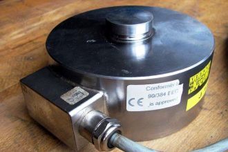
Hydraulic Load Cell

Hydraulic Load Cell Principle

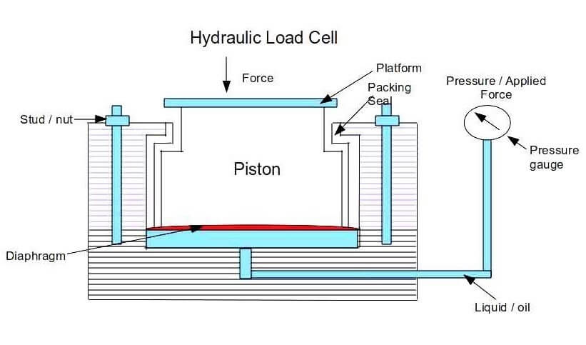
The main parts of a hydraulic load cell are as follows

  • A dirphragm
  • A piston with a loading platform (as shown in figure) placed on top of the diaphragm.
  • A liquid medium which is under a pre-loaded pressure is on the other side of the diaphragm.
  • A pressure gauge (bourdon tube type) connected to the liquid medium.

Operation of Hydraulic Load Cell

  • The force to be measured is applied to the piston.
  • The appilied force moves the piston downwards and deflects the diaphragm and this deflection of the diaphragm increases the pressure in the liquid medium (oil).
  • This increase in pressure of the liquid medium is proportional to the applied force. The increase in pressure is measured by the pressure gauge which is connected to the liquid medium.
  • The pressure is calibrated in force units and hence the indication in the pressure gauge becomes a measure of the force applied on the piston.

Note about Hydraulic Load cell:

  • As the hydraulic load cell is sensitive to pressure changes, the load cell should be adjusted to zero setting before using it to measure force.
  • This hydraulic load cell have an accuracy of the order of 0.1 percent of its scale and can measure loads upto upto 2.5*10^5 Kgf
  • The resolution is about 0.02 percent.
Don't Miss Our Updates
Be the first to get exclusive content straight to your email.
We promise not to spam you. You can unsubscribe at any time.
Invalid email address
You've successfully subscribed !

Continue Reading

Types of Angular Velocity Measurement
Loop diagram and System Inspection Lab Exercise
What is an Instrument Skid? – Example of Metering Skid
What is Arduino? Different Models of Arduino Controllers
What is HVAC System?
Why does SMPS Need isolation? – Switch Mode Power Supply
Share This Article
Facebook Whatsapp Whatsapp LinkedIn Copy Link
Share
2 Comments
  • Pradeep says:
    May 26, 2020 at 6:37 pm

    In which industry or application, this hydraulic load cell is used? How force is converted in kilo gram?

    Reply
  • Raouf Ben Ghozlane says:
    May 30, 2020 at 12:31 pm

    To Mr. Pradeep, the famous application is with the deadweight pressure gauge tester. This tool is must to be available in all instrumentation workshops, it comes with certified reference gauges or deadweights for the calibration of installed pressure gauges in the field. A link as example:<>/

    Reply

Leave a Reply Cancel reply

Your email address will not be published. Required fields are marked *

Stay Connected

128.3kFollowersLike
69.1kFollowersFollow
210kSubscribersSubscribe
38kFollowersFollow

Categories

Explore More

Ideal Guide To Sheet Metal Fabrication Manufacturing and Design
Automation in Farming & Agriculture
Lag time
Understanding the Chiller Maintenance – HVAC Tutorials
What’s the Best GPS Fleet Tracking Software and Systems?
Best Engineering Mobile Apps on Google Play & App Store
What are the Advantages & Disadvantages of CNC Milling?
Instrumentation Word Game

Keep Learning

SOA-C02 Exam Certification

Know the Best Path to Achieve SOA-C02 Exam Certification

Pressure Regulator with Flapper-Nozzle Principle

Pressure Regulator with Flapper-Nozzle Principle

Absorption chiller

Capacity Control of Absorption Chillers

Learning Programming

How to Begin Learning Programming and Succeed?

Strain Gauge Accelerometer

Strain Gauge Accelerometer

Wrong Orifice Installation

How Not to Install an Instrument and Wrong Practices

Displacement Sensing Accelerometer

Seismic Displacement Sensing Accelerometer

Linear Motion Control

What is Linear Motion Control? – Factors and Example Devices

Learn More

Breather Valve Working Principle

Breather Valve Working Principle

Level Gauge Theory

Types of Level Gauges

Power Systems Questions & Answers

Power Systems MCQ Series 6

Communicating Delta PLC Software to Simulator

wash column temperature control

Pneumatic Instrumentation

Difference between SIS, PLC and BPCS Systems

Difference between SIS, PLC and BPCS Systems

Sump Tank Level Transmitter

Problem with Sump Tank Level Transmitter

Identify Problem with Oily Water Filter Instrumentation

Identify Problem with Oily Water Filter Instrumentation

Menu

  • About
  • Privacy Policy
  • Copyright

Quick Links

  • Learn PLC
  • Helping Hand
  • Part Time Job

YouTube Subscribe

Follow US
All rights reserved. Reproduction in whole or in part without written permission is prohibited.
Welcome Back!

Sign in to your account

Username or Email Address
Password

Lost your password?