An individual transistor can be tested either in-circuit or out-of-circuit with a transistor tester. For example, let’s say that an amplifier on a particular printed circuit (PCB) board has malfunctioned. Good troubleshooting practice dictates that you do not unsolder a component from a circuit board unless you are reasonably sure that it is bad or you simply cannot isolate the problem down to a single component. When components are removed, there is a risk of damage to the PC board contacts and traces.
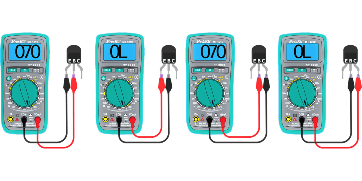
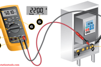
You can perform an in-circuit check of the transistor using a transistor tester similar to the one shown in below Figure. The three clip-leads are connected to the transistor terminals and the tester gives a positive indication if the transistor is good.
In-Circuit and Out-of-Circuit Tests
Case 1
If the transistor tests defective, it should be carefully removed and replaced with a known good one. An out-of-circuit check of the replacement device is usually a good idea, just to make sure it is OK. The transistor is plugged into the socket on the transistor tester for out-of-circuit tests.
Case 2
If the transistor tests good in-circuit but the circuit is not working properly, examine the circuit board for a poor connection at the collector pad or for a break in the connecting trace. A poor solder joint often results in an open or a highly resistive contact. The physical point at which you actually measure the voltage is very important in this case. For example, if you measure on the collector lead when there is an external open at the collector pad, you will measure a floating point. If you measure on the connecting trace or on the RC lead, you will read VCC. This situation is illustrated in Below Figure.
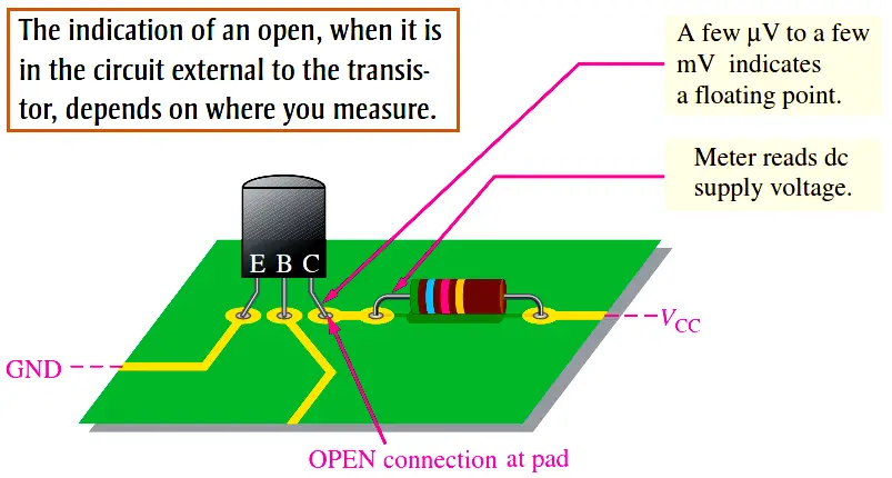
Importance of Point-of-Measurement in Troubleshooting
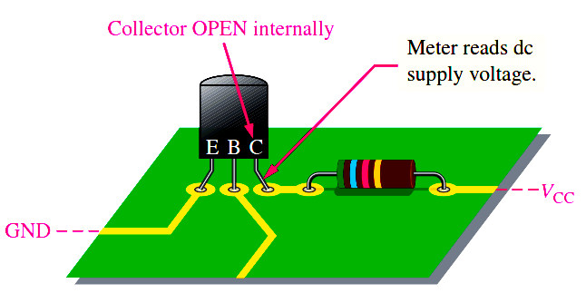
In case 2, if you had taken the initial measurement on the transistor lead itself and the open were internal to the transistor as shown in Below Figure, you would have measured VCC. This indicates a defective transistor even before the tester was used, assuming the base-to-emitter voltage is normal. This simple concept emphasizes the importance of point-of-measurement in certain troubleshooting situations.
Leakage Measurement
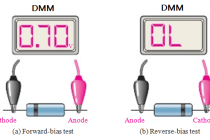
Very small leakage currents exist in all transistors and in most cases are small enough to neglect (usually nA). When a transistor is connected with thebase open (IB = 0), it is in cutoff. Ideally IC = 0; but actually there is a small current from collector to emitter, as mentioned earlier, called ICEO (collector-to-emitter current with base open). This leakage current is usually in the nA range. A faulty transistor will often have excessive leakage current and can be checked in a transistor tester. Another leakage current in transistors is the reverse collector-to-base current, ICBO. This is measured with the emitter open. If it is excessive, a shorted collector-base junction is likely.
Gain Measurement
In addition to leakage tests, the typical transistor tester also checks the βDC. A known value of IB is applied, and the resulting IC is measured. The reading will indicate the value of the IC /IB ratio, although in some units only a relative indication is given. Most testers provide for an in-circuit βDC check, so that a suspected device does not have to be removed from the circuit for testing.
Curve Tracers
A curve tracer is an oscilloscope type of instrument that can display transistor characteristics such as a family of collector curves. In addition to the measurement and display of various transistor characteristics, diode curves can also be displayed.