Gas Detectors : Approval Organizations and Guidelines
Government law, insurance companies, and/or company policy require product approvals from authorized organizations throughout the world to maintain protection of personnel and property.
This article describes the different organizations around the world and the guidelines that are used to ensure product quality and performance, thus eliminating potential hazards.
APPROVAL AGENCIES :
Approval agencies perform testing in accordance with standards developed by committees which are made up of representatives from industry, government, and approval agency authorities. These organizations differ geographically.
Below Table lists these organizations and their respective countries.
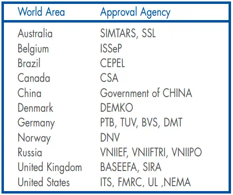
Note: Countries without approval agency may follow the IEC standards.
HAZARDOUS LOCATION PRODUCT APPROVAL :
National Electrical Code :
In North America, equipment is classified for use in hazardous locations by the National Electrical Code (NEC) as part of a Class, Division, Group, and Temperature Code.
The “Class” defines the general nature of the hazardous material in the surrounding atmosphere (List 1).
The “Division” defines the probability of hazardous material being present in an ignitable concentration in the surrounding atmosphere (List 2).
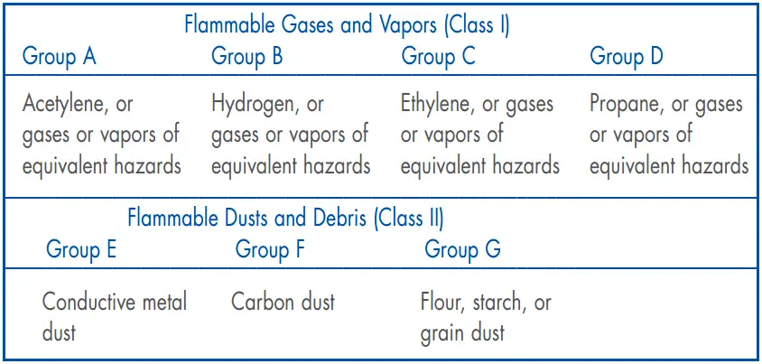
The “Group” defines the hazardous material in the surrounding atmosphere (List 3).
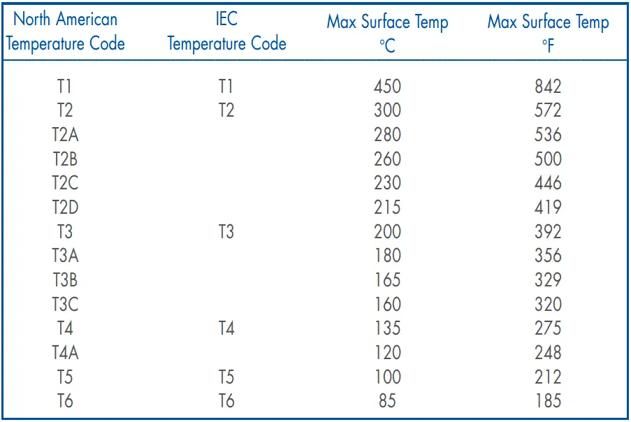
The “Temperature Code” indicates the maximum surface temperature of the apparatus or components based on –40°C to +40°C ambient temperature limits (–50°C to +40°C in Canada) (List 4). The temperature code is assumed “T5” unless specified otherwise.
List 1 : Classes defined by the National Electrical Code :
Class I : Locations where flammable gases or vapors may be present in the air in quantities sufficient to produce explosive or ignitable mixtures.
Class II : Locations where combustible or electrically conductive dusts may be present in the air in quantities sufficient to produce ignitable mixtures.
Class III : Locations where easily ignitable fibers or flyings not normally suspended in air may be present in quantities sufficient to produce ignitable mixtures.
List 2 : Divisions defined by the National Electrical Code :
Division 1 : Locations in which the probability of the atmosphere being hazardous is high due to flammable material being present continuously, intermittently, or periodically.
Division 2 : Locations which are presumed to be hazardous only in an abnormal situation.
List 3 : Groups as defined by the National Electrical Code
List 4 : Temperature Codes
INTERNATIONAL ELECTROTECHNICAL COMMITTEE (IEC) :
The IEC consists of close to 40 countries, attempting to establish international standards for electrical products.
The IEC uses “Gas Groups,” “Zones,” and “Temperature Codes” to classify equipment for use in hazardous locations.
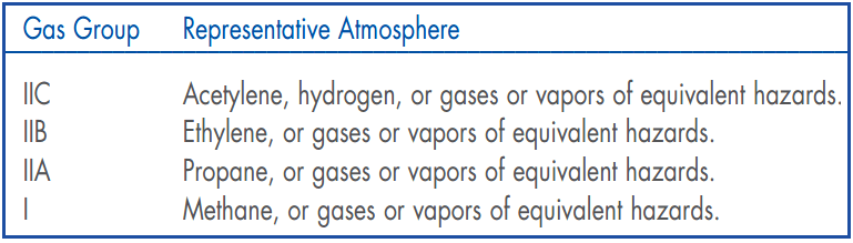
The “Gas Groups” define the hazardous material in the surrounding atmosphere (List 5).
The “Zone” defines the probability of hazardous material being present in an ignitable concentration in the surrounding atmosphere (List 6).
The “Temperature Code” indicates the maximum surface temperature of the apparatus or components based on –20°C to +40°C ambient temperature limits (List 4).
List 5 : Gas Groups defined by the IEC
List 6 : IEC Zones
Zone 0 : An explosive concentration of gas or vapor is present continuously or is present for long periods of time.
Zone 1 : An explosive concentration of gas or vapor is likely to be present for short periods of time under normal operating conditions.
Zone 2 : An explosive concentration of gas or vapor is likely to be present for very short periods of time due to an abnormal condition.
Zone 20 : An explosive atmosphere of dust is present continuously or is present for long periods of time.
Zone 21 : An explosive atmosphere of dust is likely to be present for short periods of time under normal operating conditions.
Zone 22 : An explosive atmosphere of dust is likely to be present for very short periods of time due to an abnormal condition.
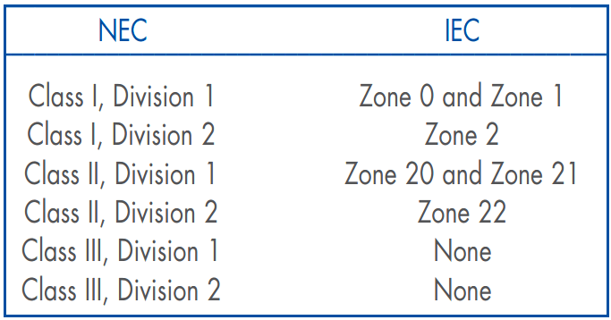
Comparison of Classification Codes
Below Table presents a comparison of the National Electrical Code and International Electrotechnical Committee hazardous location classification nomenclatures.
Source : det-tronics