Inst ToolsInst ToolsInst Tools
  • Ask
  • Courses
  • Videos
  • Q & A
    • Interview
      • Instrumentation
      • Electronics
      • Electrical
      • Practical Questions
    • MCQ
      • Instrumentation MCQ
      • Electrical MCQ
      • Electronics MCQ
      • Control Systems MCQ
      • Analog Electronics MCQ
      • Digital Electronics MCQ
      • Power Electronics MCQ
      • Microprocessor MCQ
      • Multiple Choice Questions
  • EE
    • Electronics
      • Electronics Q & A
      • Electronic Basics
      • Electronic Devices & Circuits
      • Electronics Animation
      • Digital Electronics
    • Electrical
      • Electrical Basics
      • Electrical Q & A
      • Power Electronics
      • Electrical Machines
      • Electrical Animation
      • Power Systems
      • Switchgear & Protection
      • Transmission & Distribution
  • Measure
    • Control Valves
    • Calibration
    • Temperature
    • Pressure
    • Flow
    • Level
    • Analyzers
    • Switches
    • Vibration
    • Solenoid Valve
  • Control
    • PLC Tutorials
    • Control Systems
    • Safety Instrumented System (SIS)
    • Communication
    • Fire & Gas System
  • More
    • Design
    • Tools
    • Animation
    • Basics
    • Formulas
    • Standards
    • TextBooks
    • Common
    • Software
    • Excel Tools
    • Erection & Commissioning
    • Process Fundamentals
    • Videos
    • Books
Search
All rights reserved. Reproduction in whole or in part without written permission is prohibited.
Reading: Gage and Absolute Pressure Transmitters Principle
Share
Notification Show More
Font ResizerAa
Inst ToolsInst Tools
Font ResizerAa
  • Courses
  • PLC Tutorials
  • Control Systems
Search
  • Ask
  • Courses
  • Videos
  • Q & A
    • Interview
    • MCQ
  • EE
    • Electronics
    • Electrical
  • Measure
    • Control Valves
    • Calibration
    • Temperature
    • Pressure
    • Flow
    • Level
    • Analyzers
    • Switches
    • Vibration
    • Solenoid Valve
  • Control
    • PLC Tutorials
    • Control Systems
    • Safety Instrumented System (SIS)
    • Communication
    • Fire & Gas System
  • More
    • Design
    • Tools
    • Animation
    • Basics
    • Formulas
    • Standards
    • TextBooks
    • Common
    • Software
    • Excel Tools
    • Erection & Commissioning
    • Process Fundamentals
    • Videos
    • Books
Follow US
All rights reserved. Reproduction in whole or in part without written permission is prohibited.
Inst Tools > Blog > Pressure Measurement > Gage and Absolute Pressure Transmitters Principle

Gage and Absolute Pressure Transmitters Principle

Last updated: May 15, 2019 5:47 pm
Editorial Staff
Pressure Measurement
1 Comment
Share
3 Min Read
SHARE

Gage and Absolute Pressure Transmitters :

Contents
Sensor Design for Gage Pressure MeasurementSensor Design for Absolute Pressure MeasurementPressure Transmitter Block Diagram :

Sensor Design for Gage Pressure Measurement
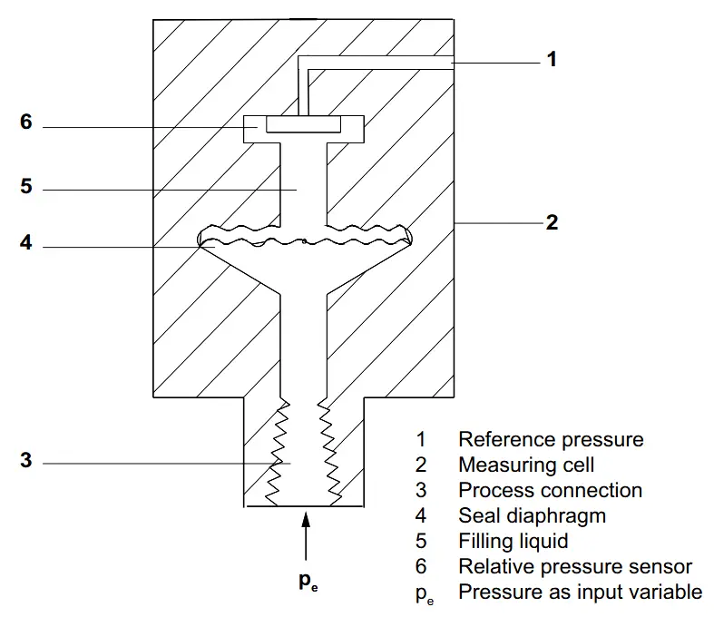
gage pressure transmitter principle

The input pressure (pe) is transferred to the gage pressure sensor (6) via the seal diaphragm (4) and the filling liquid (5), displacing its measuring diaphragm.

The displacement changes the resistance value of the four piezo resistors in the measuring diaphragm in a bridge circuit.

The change in the resistance causes a bridge output voltage proportional to the input pressure.

The transmitters with spans ≤ 63 bar measure the input pressure against atmosphere, those with spans ≥ 160 bar against vacuum.

Sensor Design for Absolute Pressure Measurement

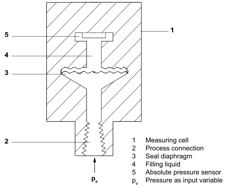
absolute pressure transmitter principle

The input pressure (pe) is transferred to the absolute pressure sensor (5) via the seal diaphragm (3) and the filling liquid (4), displacing its measuring diaphragm.

The displacement changes the resistance value of the four piezo resistors in the measuring diaphragm in a bridge circuit.

The change in the resistance causes a bridge output voltage proportional to the input pressure.

Pressure Transmitter Block Diagram :

Pressure Transmitter Working Principle

Pressure Transmitter Parts

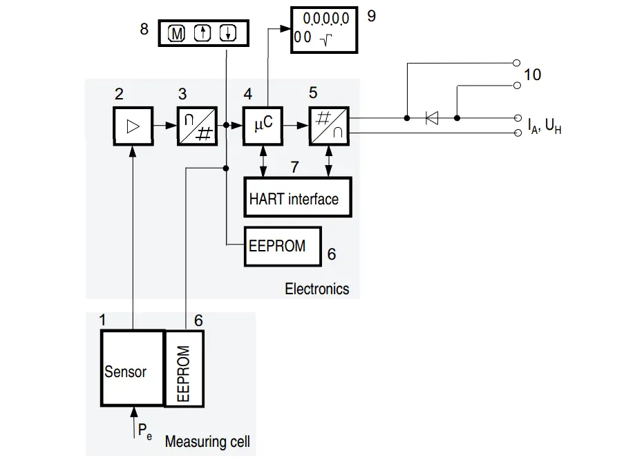
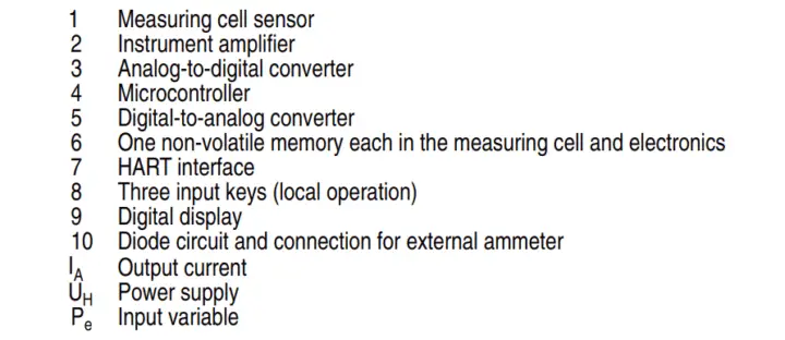
The input pressure is converted into an electrical signal by the sensor (1). This signal is amplified by the measuring amplifier (2) and digitalized in an analog to digital converter (3). The digital signal is analyzed in a microcontroller (4) and corrected with regard to linearity and thermal characteristics.

In a digital to analog converter (5) it is then converted into the output current of 4 to 20 mA. A diode circuit provides reverse voltage protection. You can make an uninterrupted current measurement with a low ohm ammeter at the connection (10).

The data specific to the measuring cell, the electronic data and parameter settings are stored in two non-volatile memories (6). The first memory is linked with the measuring cell, the second with the electronics.

The buttons (8) can be used to call up individual functions, socalled modes. If you have a device with a digital display (9), you can use this to track mode settings and other messages. The basic mode settings can be changed with a computer via the HART modem (7).

Reference : Siemens Manual, Image Credits : Siemens
Don't Miss Our Updates
Be the first to get exclusive content straight to your email.
We promise not to spam you. You can unsubscribe at any time.
Invalid email address
You've successfully subscribed !
Remote Diaphragm Seal Transmitter for Vacuum Application
Basics of Differential Pressure Transmitters
C-Bourdon Tube Pressure Gauge Theory
Uncertainty Calculations of Pressure Calibration
Diaphragm Pressure Sensors
Share This Article
Facebook Whatsapp Whatsapp LinkedIn Copy Link
Share
1 Comment
  • Jitendra meena says:
    August 26, 2017 at 1:33 pm

    Very useful information.
    But sir how to identify that it is Rosemont gauge pressure or absolute pressure transmitter in 2051c series.

    Reply

Leave a Reply Cancel reply

Your email address will not be published. Required fields are marked *

Stay Connected

128.3kFollowersLike
69.1kFollowersFollow
208kSubscribersSubscribe
38kFollowersFollow

Categories

Recent Comments

  • Guifty Shimica on Top Non-PLC Certification Courses for Automation Professionals
  • Guifty Shimica on Top Non-PLC Certification Courses for Automation Professionals
  • MIHARITSOA Aina Sitraka on Top Non-PLC Certification Courses for Automation Professionals
  • Vaishnavi on Free Instrumentation Course for Trainee Engineers

Related Articles

Types of Pressure

Types of Pressure – Instrument Questions and Answers

U Tube Manometer Principle

U-tube Manometer Principle

Pressure Transmitters Filled impulse lines

Pressure Transmitters Filled impulse lines

inductance transducer

Inductance Type Pressure Transducers Principle

Bourdon Tube Pressure Gauge Parts

Bourdon Tube Pressure Gauge

Differential Pressure Flow Transmitter Interview Questions

Interview Questions on Differential Pressure Flow Transmitter

Strain Gauge Pressure Sensor Principle

Strain Gauge Pressure Sensor Principle

Pressure Gauge Installation

Pressure Gauge Installation at Pump Discharge

More Articles

Control Systems Stability and Algebraic Criteria

Routh-Hurwitz Stability Criterion

PLC Pressure Switch Ladder Diagram

Relays in Ladder Logic Tutorials

Control valve sizing

Relative Flow Capacity of a Valve

HVAC Questions & Answers

HVAC Questions & Answers

Add On Instructions Programming – Analog Input Devices in Studio 5000

Why Are Charcoal and Salt Added to an Earthing Pit

Why Are Charcoal and Salt Added to an Earthing Pit?

DP Transmitter Wet Leg Compensating Impulse Line

Questions on DP Transmitter Wet Leg Compensating Impulse Line

Capacitive Transducers Objective Questions

Capacitive Transducers Objective Questions

Follow US
All rights reserved. Reproduction in whole or in part without written permission is prohibited.
Welcome Back!

Sign in to your account

Username or Email Address
Password

Lost your password?