This article will discuss the application of Programmable Logic Controller (PLC) in a water level monitoring system for Dams. Using the XG-5000 PLC software, this system is designed to provide early warnings through indicator alarms when water levels reach critical points. Additionally, the system will automatically activate control actions such as operating Water Pumps and opening Gates to maintain dam safety.
Program Objective
The system continuously monitors the water level.
Level 1:
- Alarm Level 1 is Active as an early warning.
Level 2:
- Alarm Level 2 is Active.
- The drain valve is Open to reduce water flow.
- The water pump turns ON to help lower the water level.
Level 3:
- Alarm Level 3 is Active.
- The first dam gate opens.
Level 4:
- Alarm Level 4 is Active.
- The second dam gate is Open.
Level 5:
- Alarm Level 5 is Active.
- All dam gates (3) are Open.
Flood Warning System
Program Inputs and Outputs
| No | Comment | Input (I) | Output(Q) | Memory Bits | Timer |
| 1 | START | P0000 | |||
| 2 | STOP | P0001 | |||
| 3 | SENS_LEVEL1 | P0002 | |||
| 4 | SENS_LEVEL2 | P0003 | |||
| 5 | SENS_LEVEL3 | P0004 | |||
| 6 | SENS_LEVEL4 | P0005 | |||
| 7 | SENS_LEVEL5 | P0006 | |||
| 8 | ALARM_LEVEL1 | P0040 | |||
| 9 | ALARM_LEVEL2 | P0041 | |||
| 10 | VALVE | P0045 | |||
| 11 | PUMP | P0046 | |||
| 12 | ALARM_LEVEL3 | P0004 | |||
| 13 | GATE1_OPEN | P0047 | |||
| 14 | ALARM_LEVEL4 | P0043 | |||
| 15 | GATE2_OPEN | P0048 | |||
| 16 | ALARM_LEVEL5 | P0044 | |||
| 17 | GATE3_OPEN | P0049 | |||
| 18 | TIMER_PUMP | T0000 | |||
| 19 | SYSTEM_ON | M0000 | |||
| 20 | IR_GATE1 | M0001 | |||
| 21 | IR_GATE2 | M0002 |
Programmable Logic Controller
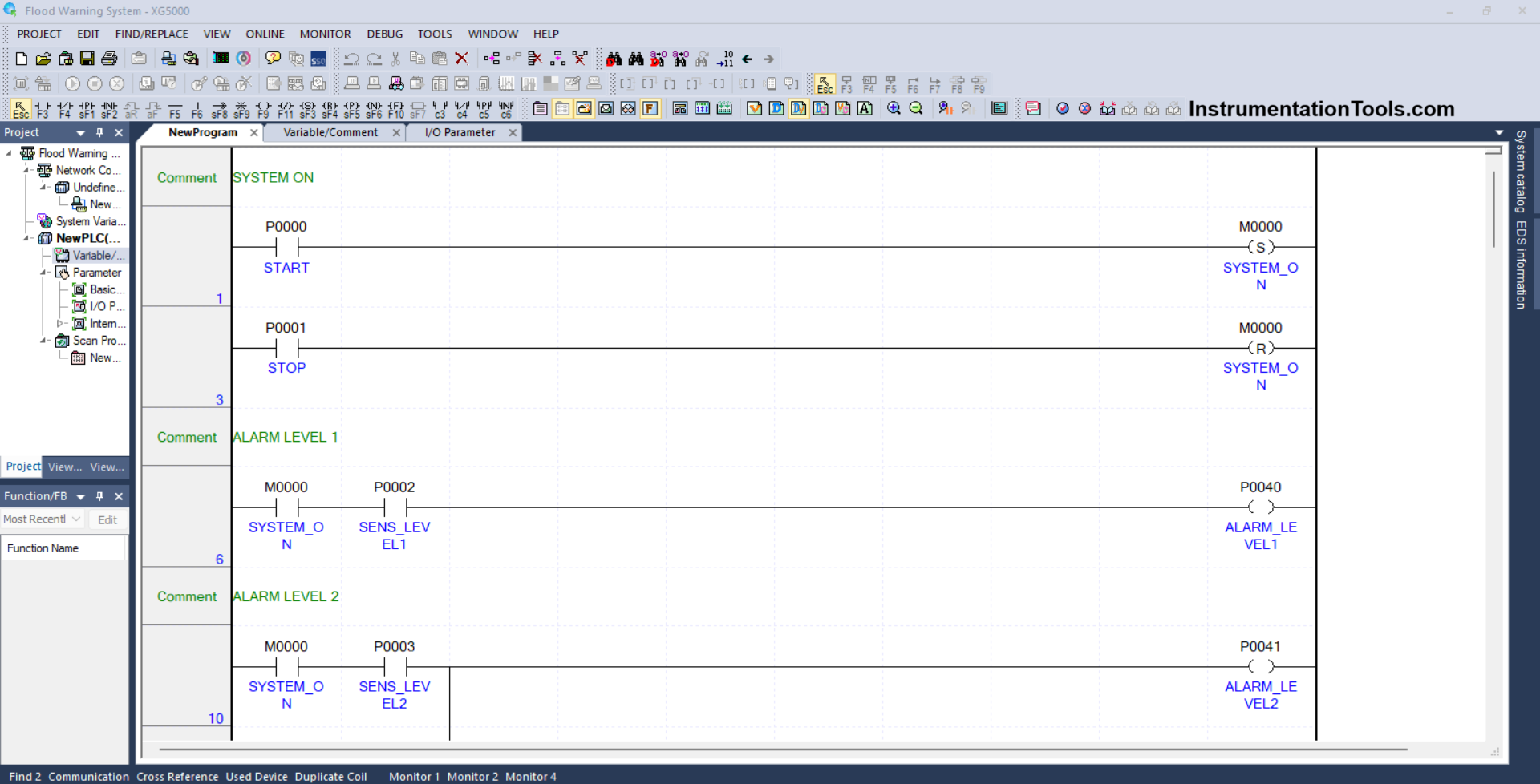
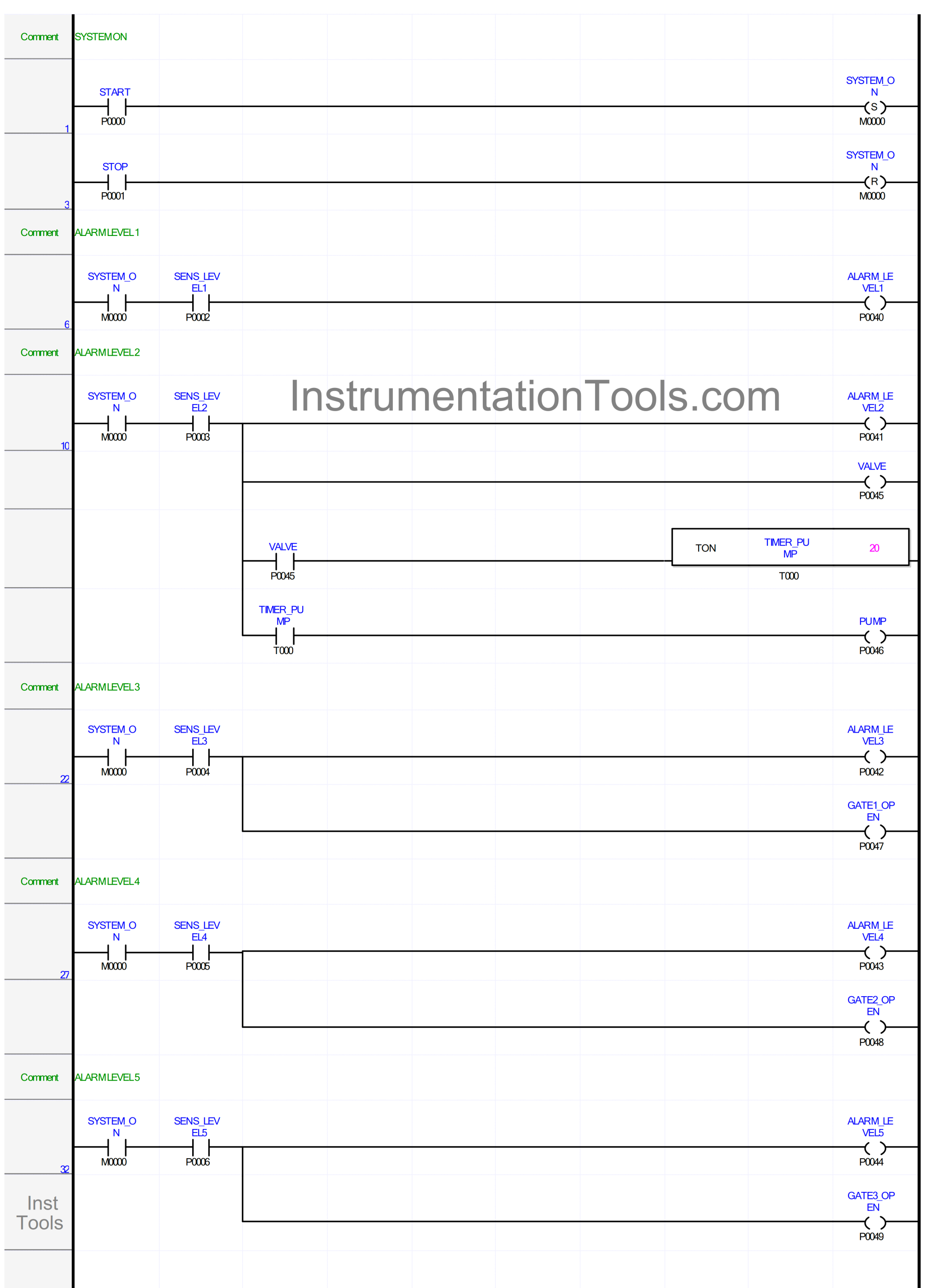
RUNG 1 (SYSTEM ON)
In this Rung, the memory bit SYSTEM_ON (M0000) will be in the HIGH state if the button START (P0000) Pressed. The memory bit SYSTEM_ON (M0000) will remain in the HIGH state even though the button START (P0000) has been Released, because it uses the SET Coil Instruction.
RUNG 3
In this Rung, if the button STOP (P0001) is Pressed, the memory bit SYSTEM_ON (M0000) will be in the LOW state. Because it uses the RESET Coil Instruction.
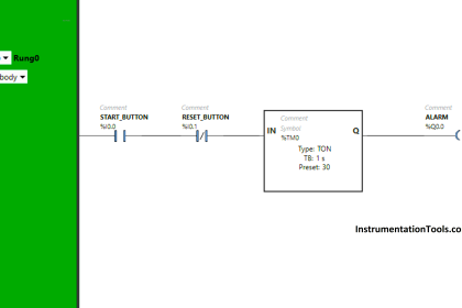
RUNG 6 (ALARM LEVEL 1)
In this Rung, the output ALARM_LEVEL1 (P0040) will be ON if the NO contact of the memory bit SYSTEM_ON (M0000) and the sensor SENS_LEVEL1 (P0002) are in the HIGH state.
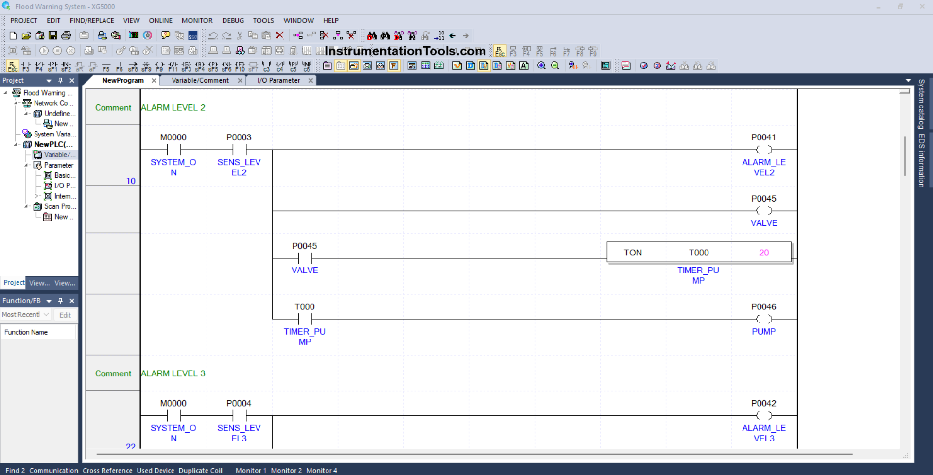
RUNG 10 (ALARM LEVEL 2)
In this Rung, the output ALARM_LEVEL2 (P0041) will be ON and the output VALVE (P0045) will be OPEN, when the NO contact of the memory bit SYSTEM_ON (M0000) and the sensor SENS_LEVEL2 (P0003) are in the HIGH state.
And when the NO contact of the VALVE (P0045) is in the HIGH state, the timer TIMER_PUMP (T0000) will Start counting up to 2 seconds. The output PUMP (P0046) will be ON after the TIMER_PUMP (T0000) Timer has finished counting.
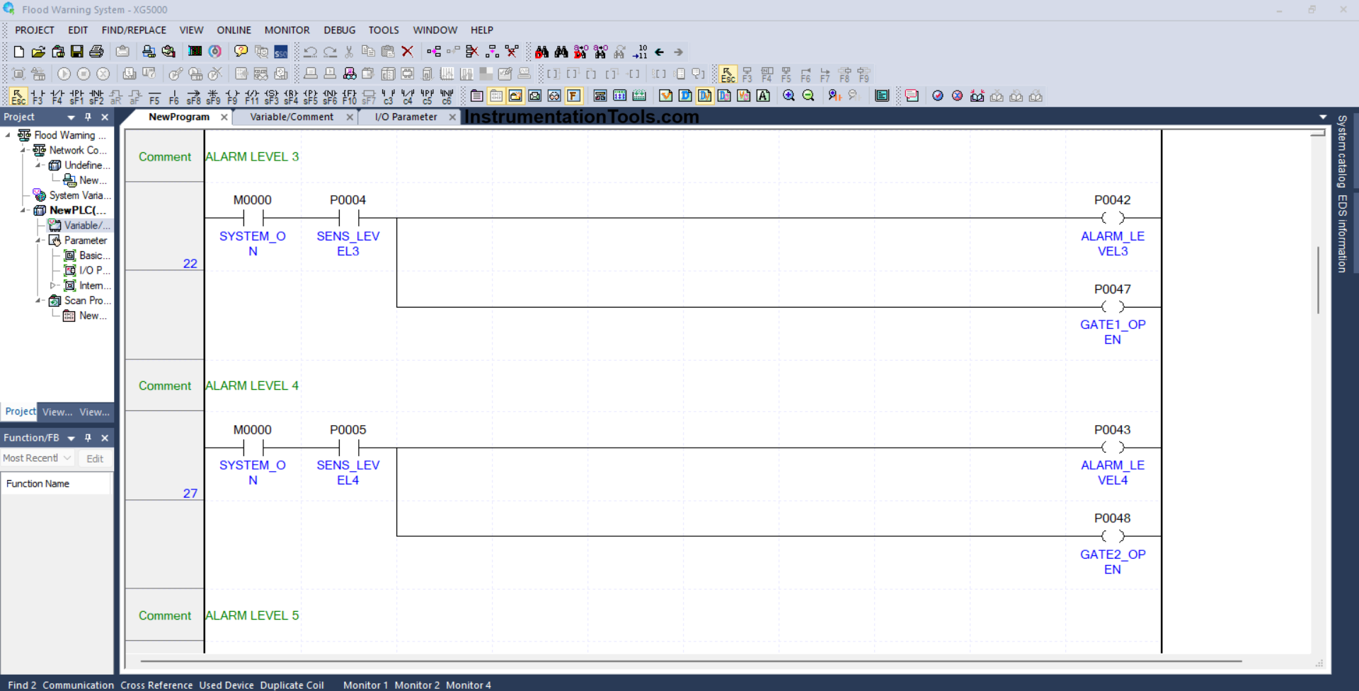
RUNG 22 (ALARM LEVEL 3)
In this Rung, the output ALARM_LEVEL3 (P0004) will be ON and the output GATE1_OPEN (P0047) will be OPEN if the NO contact of the memory bit SYSTEM_ON (M0000) and the sensor SENS_LEVEL3 (P0004) are in the HIGH state.
RUNG 27 (ALARM LEVEL 4)
In this Rung, the output ALARM_LEVEL4 (P0043) will be ON and the output GATE2_OPEN (P0048) will be OPEN if the NO contact of the memory bit SYSTEM_ON (M0000) and the sensor SENS_LEVEL4 (P0005) are in the HIGH state.
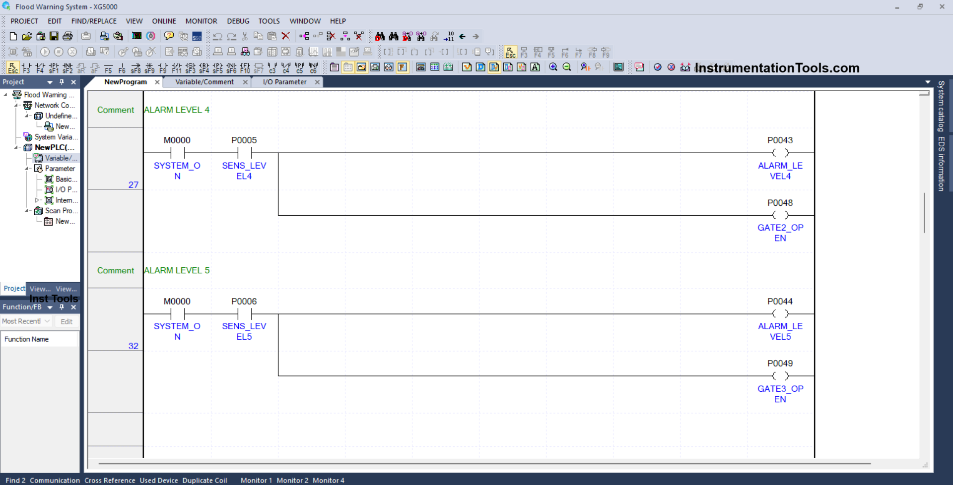
RUNG 32 (ALARM LEVEL 5)
In this Rung, the output ALARM_LEVEL5 (P0044) will be ON and the output GATE3_OPEN (P0049) will be OPEN if the NO contact of the memory bit SYSTEM_ON (M0000) and the sensor SENS_LEVEL5 (P0006) are in the HIGH state.
Read Next:
- Argonite & CO2 Flooding System Operation
- What is a Fail-safe in a Siemens PLC System?
- Siemens LOGO PLC Programming Course
- How to Download GX Works Software?
- Which Connection is Best for PLC Panel?